Research on Overload Protection Technology for Accelerator High-Voltage Power Supplies
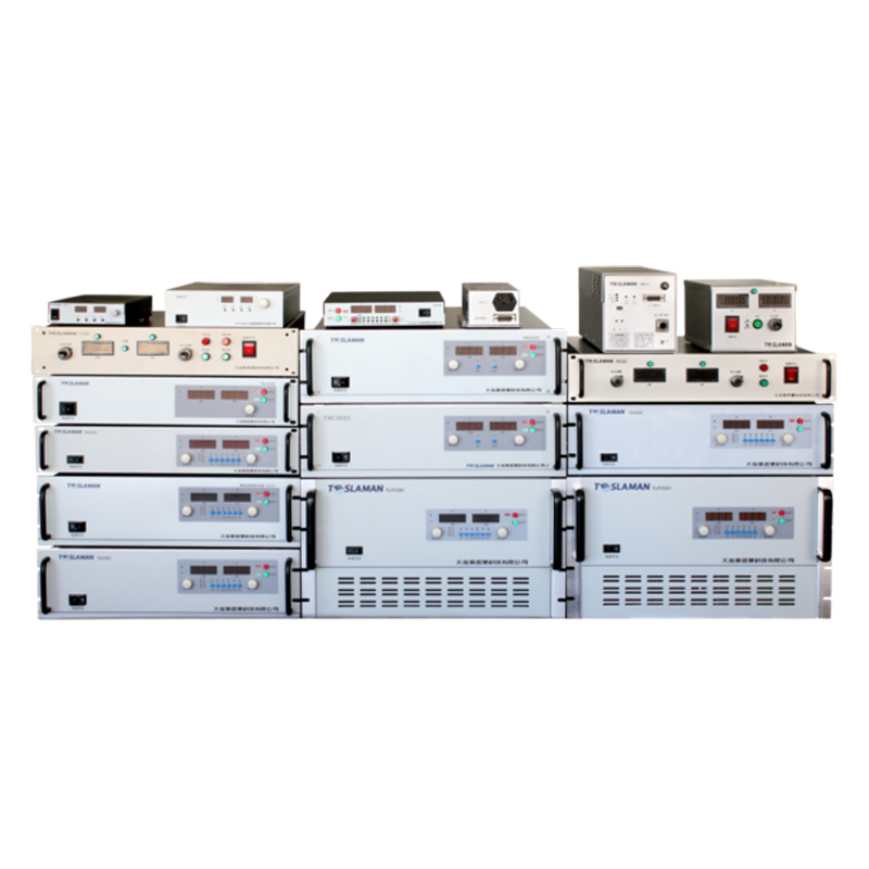
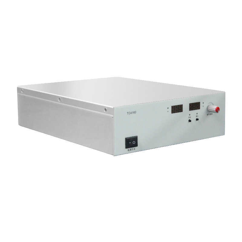
In high-end scientific and industrial equipment such as particle accelerators and medical irradiation devices, the stability of high-voltage power supplies directly determines system reliability and longevity. These power supplies typically require outputs ranging from tens to hundreds of kilovolts, with currents reaching hundreds of milliamps. Their load characteristics are complex and susceptible to transient faults such as short circuits and arcs. Overload protection, as a core safety mechanism, must respond to anomalies within microseconds to prevent cascading failures like high-voltage breakdown and power device burnout.
1. Overload Risk Characteristics of Accelerator High-Voltage Power Supplies
1. High-Energy Transient Current Surges
When a short circuit occurs at the output end (e.g., abnormal discharge of internal electrodes), transient currents of tens of kiloamperes may arise. Such currents can cause overheating and breakdown of power switches (e.g., IGBTs, MOSFETs) within microseconds, potentially leading to insulation failure in high-voltage generators.
2. Systemic Cascading Failure Risks
Accelerator power systems often adopt multi-stage topologies, such as main high-voltage supplies (-350 kV/60 mA) and filament supplies (10 V/3 A) floating at high potentials. If overload in the main supply is not isolated promptly, faults can propagate to auxiliary supplies via common-mode interference, causing entire power chains to collapse.
2. Limitations of Traditional Overload Protection Schemes
1. Response Delay Issues
Software Protection: Relies on microprocessors (e.g., STM32F103) to sample current signals, but signal processing and algorithm decisions take milliseconds, insufficient to block microsecond-level transient overcurrents.
Resistive Sampling: Sampling resistors incur high losses under high power (e.g., milliohm-level resistors dissipate kilowatts instantly at kiloampere currents), and signal transmission delays cause protection lag.
2. Temperature and Precision Constraints
Traditional drive protection judges overcurrent by detecting switch tube voltage drops, but threshold drift due to temperature variations may lead to false or missed triggers.
3. Evolution of Core Modern Overload Protection Technologies
1. Hardware-Level Parallel Protection Architecture
CPLD Fast Shutdown Circuits: Complex programmable logic devices (e.g., EMP240T100C5N) enable hardware-parallel processing, compressing response time to <100 nanoseconds. If current sensors (e.g., Hall sensors) detect anomalies, the CPLD directly bypasses the main controller to send shutdown signals to the drive module, cutting off IGBT gate pulses.
Pulse-by-Pulse Current Limiting: Real-time comparison of drive tube current with thresholds in each switching cycle. If exceeded, the current pulse is terminated immediately to prevent cumulative damage from transformer magnetic saturation.
2. Multi-Stage Protection Strategy Integration
Graded Threshold Triggering:
Overload Protection: Uses inverse time characteristics. For example, at 1.2× rated current, action time is <0.1 seconds; at 1.4×, it shortens to 28.6 ms (Table 1).
Short-Circuit Protection: Independent high thresholds (e.g., 8-10× rated current) trigger instantaneous shutdown.
Dual Redundancy: Primary protection (e.g., CPLD) and secondary circuits (e.g., LM2903 fast-identification) operate in parallel; triggering either executes shutdown.
Table 1: Example of Inverse-Time Overload Protection (Rated Current: 400 A)
| Overload Multiple | Action Time (Gear 8) |
|-------------------|----------------------|
| 1.2× | 33.3 ms |
| 1.4× | 28.6 ms |
| 2.0× | <0.1 s (short-circuit)|
3. New Devices and Materials Applications
SiC MOSFETs Replace Silicon Devices: Silicon carbide power tubes leverage high bandgap width (3× silicon), high critical breakdown field strength (≥1200 V), and low on-resistance to withstand higher di/dt and transient thermal stress. Their switching frequency exceeds 50 kHz (vs. 20 kHz for silicon IGBTs), reducing filter inductor size while significantly shortening short-circuit recovery time.
Non-Contact Sampling: Rogowski coils or fluxgate sensors enable lossless current signal acquisition, improving signal-to-noise ratio and response speed.
4. System-Level Optimization and Future Trends
1. Fault Diagnosis and Adaptive Adjustment
Modern accelerator power supplies integrate multi-parameter monitoring (e.g., coolant flow, temperature, gate drive waveforms), transmitting data via RJ45 to human-machine interfaces. Historical data trains fault models to dynamically adjust overload thresholds (e.g., lowering thresholds in high-temperature environments).
2. High-Temperature and Integrated Design
SiC devices tolerate temperatures >200°C, simplifying thermal management. Their high power density enables integration of drive, protection, and detection circuits onto a single PCB adapter, reducing signal path delays.
--
Conclusion
Overload protection for accelerator high-voltage power supplies has evolved from simple fuses and software solutions to integrated approaches combining hardware-parallel shutdown, multi-stage thresholds, and wide-bandgap semiconductors. As SiC costs decline and adaptive algorithms proliferate, future protection circuits will achieve faster response and higher reliability, enabling zero-failure safety for critical scientific facilities.
