Electromagnetic Compatibility Enhancement Scheme for High-Voltage Power Supplies in Lithography Machines
As core equipment in semiconductor manufacturing, the electromagnetic compatibility (EMC) of high-voltage power supplies in lithography machines directly impacts exposure accuracy and system stability. Transient interference, harmonic noise, and radiation emissions generated by high-voltage power supplies may disrupt precision control systems and sensors. This article proposes a comprehensive EMC enhancement scheme from three perspectives: design optimization, material selection, and verification testing.
1. EMC Challenges in High-Voltage Power Supplies
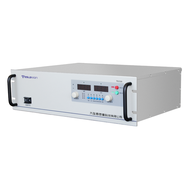
Lithography high-voltage power supplies provide stable kilovolt-level voltage to light sources (e.g., excimer lasers), with three primary interference sources:
1. Switching Noise: Rapid switching of power conversion circuits (e.g., DC-DC converters) generates high-frequency harmonics, interfering with peripheral circuits via conduction and radiation.
2. Common-Mode Interference: Parasitic capacitance coupling between high-voltage outputs and ground forms common-mode currents, affecting sensitive signal processing circuits (e.g., position sensor feedback).
3. Ground Current Return: Ground potential fluctuations caused by impedance differences in multi-stage circuits lead to control signal distortion.
2. Key Design Optimization Technologies
1. Layered Grounding and Shielding
• Grounding Strategy: Use three separated ground lines—signal ground (low-level), noise ground (power loop), and safety ground (chassis)—connected at a single point to reduce common-impedance coupling. High-frequency circuits (>10MHz) employ multi-point ground planes to shorten return paths.
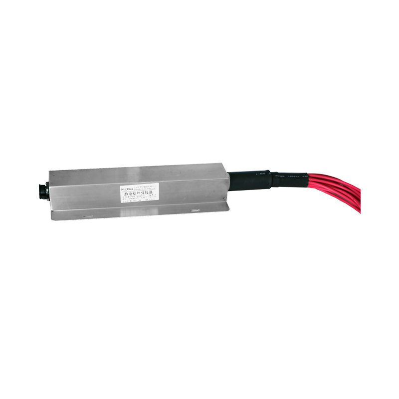
• Active Shielding: Double-layer copper braided shielding for high-voltage cables: inner layer single-end grounded to eliminate capacitive coupling; outer layer multi-point grounded to suppress radiation. Sensitive circuits (e.g., FPGA control boards) are shielded with permalloy magnetic shields to attenuate low-frequency magnetic fields.
2. Filtering and Noise Suppression
• Conduction Filtering: Three-stage filtering at power input—EMI filter (>150kHz broadband noise), PFC circuit (power factor correction), and common-mode choke (common-mode current suppression)—with >60dB insertion loss.
• Transient Suppression: Parallel RC snubber circuits across MOSFET switches limit voltage spikes to <10%; TVS diodes at outputs absorb nanosecond-level surges.
• Signal Conditioning: Differential signals use isolation amplifiers with high CMRR (>120dB) to suppress ±275V common-mode interference.
3. PCB and Wiring Optimization
• Stackup Design: Power boards adopt ≥4-layer PCBs with dedicated power and ground layers to reduce parasitic inductance. High-voltage traces are guarded with spacing ≥3× trace width to prevent creepage.
• Critical Path Control: Strong/weak signal traces routed orthogonally to avoid crosstalk; clock signal length ≤λ/20 (λ: wavelength) with serpentine length matching.
• Decoupling Capacitor Layout: Each IC power pin uses a parallel combination of ceramic (100nF) and electrolytic capacitors (10μF), with high-frequency noise absorption paths ≤5mm.
3. Material and Structural Enhancement
1. High-Frequency Magnetic Materials: DC-DC converters use Fe-Si-Al cores (μr>60) to reduce eddy current losses; transformers adopt triple-insulated wires with polyimide interlayer tape.
2. Conductive Gaskets: Beryllium-copper finger gaskets at chassis seams maintain RF continuity (shielding effectiveness >90dB) with gaps ≤1mm.
3. Thermal-EMC Synergy: Conductive anodized heat sinks connected to chassis via thermal tapes prevent electrostatic accumulation; fan power lines wind around ferrite rings (impedance >1kΩ@100MHz).
4. Verification and Testing
1. Pre-Compliance Testing:
• Conducted Emission: Per CISPR 32, measure power line interference (150kHz~30MHz) using LISN, requiring >20dB below limits.
• Radiated Immunity: Apply 10V/m field strength (80MHz~1GHz) in an anechoic chamber, monitoring positioning error (<±0.1nm).
2. Fault Injection Testing:
• ESD: ±8kV contact discharge, ±15kV air discharge; no system reset or data loss post-test.
• EFT: Inject ±2kV burst pulses (5kHz) into power lines; output ripple <0.1%.
5. Conclusion
EMC enhancement for lithography high-voltage power supplies requires a holistic approach targeting interference source suppression–propagation path blocking–sensitive terminal protection. Layered grounding and active shielding reduce radiation coupling; filtering networks and buffer circuits optimize conduction paths. Material selection and structural design enhance inherent immunity. Rigorous EMC testing validates the design, ensuring stable power delivery for nanoscale exposure precision in complex electromagnetic environments.