Research on Low-Ripple Resonant Topology for High-Voltage Power Supply in Lithography Machines
As the core equipment of semiconductor manufacturing, the exposure accuracy of lithography machines directly determines the linewidth limit of chips. The ripple performance of high-voltage power supplies is a key factor affecting exposure quality—ripples introduce electric field disturbances, causing electron beam scanning deviations or laser wavelength drift. Traditional switching power supply topologies typically generate ripples of tens to hundreds of millivolts, while high-end lithography machines require a ripple coefficient below 0.01% (ripple peak-to-peak value <1 V at 10 kV output). Resonant topology has become the mainstream solution to overcome this bottleneck, leveraging soft-switching characteristics and ripple cancellation mechanisms.
1. Limitations of Traditional Topologies vs. Advantages of Resonant Topologies
1. Bottlenecks of Linear Power Supplies
Although linear power supplies offer low ripple (typically <10 mV), their efficiency is only 30%–50%. At 10 kV/30 mA output, power loss can reach 300 W, and the bulky heat dissipation system cannot meet the miniaturization requirements of lithography machines.
2. High-Frequency Interference in Switching Power Supplies
Traditional Buck-Boost topologies generate high-frequency oscillations (1–10 MHz) due to hard-switching actions. Parasitic capacitances and line inductances form resonant spikes, superimposing ultra-high-frequency ripples on the output. Even with multi-stage LC filtering, controlling ripples below 1 V remains challenging.
3. Breakthrough of Resonant Topologies
Resonant converters (e.g., LLC, LCC) utilize Zero-Voltage Switching (ZVS) and Zero-Current Switching (ZCS) to eliminate switching losses:
• LLC Topology: Achieves soft-switching via transformer leakage inductance and resonant capacitance, reducing theoretical ripples below 0.5% at operating frequencies (67–200 kHz).
• Dual-Phase Parallel Architecture: Two half-bridge inverters with a 90° phase shift cancel output pulsations. Experiments show that single-path ripples of 120 mV at 13 kHz decrease to 15 mV after parallel connection.
Table: Performance Comparison of Different Topologies
Topology Type Efficiency Ripple (p-p) Application Scenario
Linear Power Supply 30–50% <10 mV Low-power precision instruments
Traditional Switching 70–85% 50–200 mV General industrial equipment
LLC Resonant Converter 90–95% 20–50 mV Medium-high voltage systems
Dual-Phase Resonant 92–98% <20 mV Lithography machines, particle accelerators
2. Core Technological Breakthroughs in Resonant Topologies
1. Ripple Cancellation Architecture
Lithography high-voltage power supplies adopt dual independent half-bridge inverters:
• Each path is powered by a three-phase fully controlled rectifier, with IGBT-driven square waves precisely offset by 90°.
• A voltage-tracking circuit detects output differences in real-time, ensuring amplitude error <0.1% via PID phase-shift adjustment.
2. Voltage Doubler Rectification Optimization
A 12-stage voltage doubler rectifier boosts 67 kHz AC to 10 kV:
V_{out} = 2n \cdot (V_{AC} V_D)
where V_D is the diode forward voltage. Using ultra-fast recovery diodes (V_D \leq 0.3\ \text{V}), the theoretical voltage drop is <3.6 V. Combined with resonant inductance compensation (formula: \Delta U = \frac{I_o}{4\pi f C}), ripples can be controlled below 2 V.
3. Magnetic Components and Layout Optimization
• Transformer Design: Segment winding with honeycomb structure reduces distributed capacitance by 30%; nanocrystalline cores minimize eddy current losses.
• Potting Process: Epoxy resin encapsulation suppresses partial discharge-induced current spikes.
Table: Magnetic Component Optimization Measures and Effects
Optimization Measure Technical Principle Ripple Suppression Effect
Honeycomb Winding Segmented Coils Reduces interlayer capacitance, dampens high-frequency oscillations 40% HF noise attenuation
Nanocrystalline Core High permeability, lowers core losses Reduces temperature rise by 15°C
Resonant Inductance Compensation Offsets charge leakage fluctuations in voltage doublers 50% ripple reduction
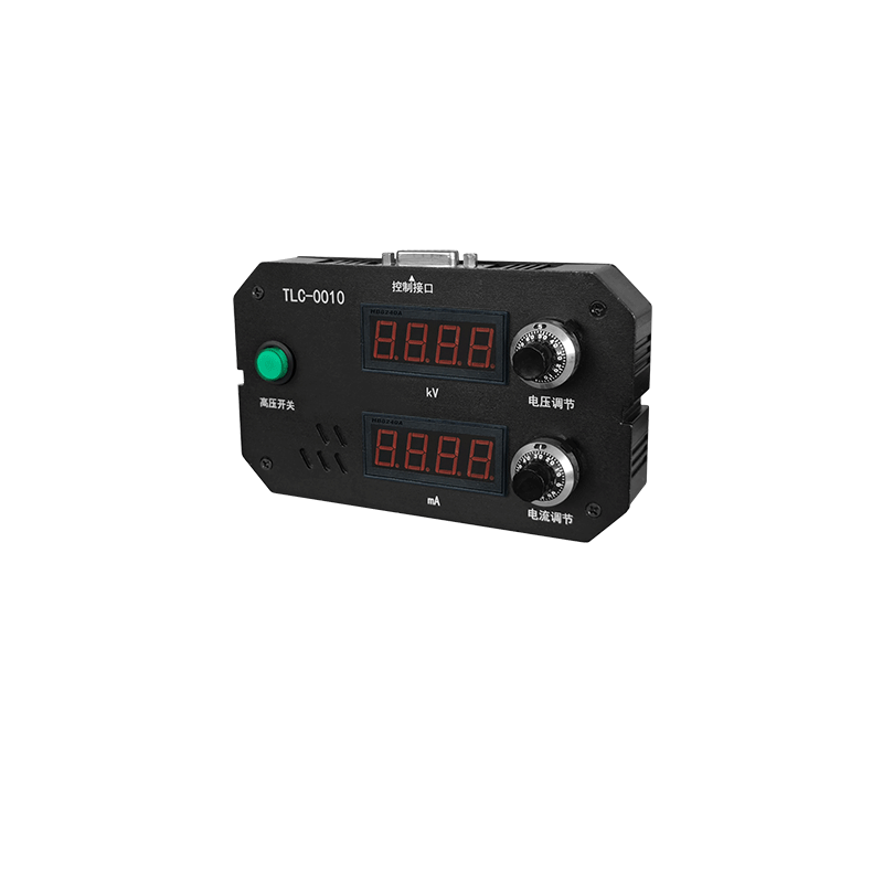
4. Digital Control and Feedback
51-series microcontrollers enable closed-loop control:
• Output voltage sampling → error amplification → MOSFET drive pulse width adjustment.
• Multi-stage feedback (voltage, current, temperature) improves system ripple stability by 80%.
3. Engineering Validation and Future Trends
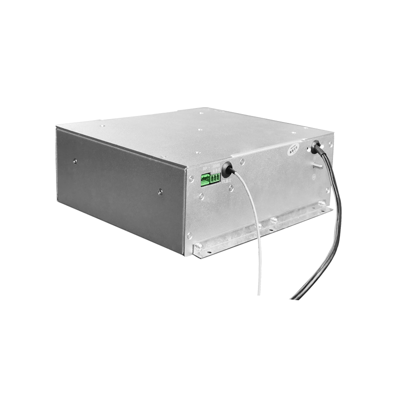
Test data from a lithography high-voltage module:
• Input: 12 V DC, Output: 10 kV/30 μA
• Ripple: 1.8 V (p-p), Efficiency: 94%
• Temperature Drift: <80 ppm/℃ (meets thermal stability requirements for nanoscale exposure)
Future directions:
1. GaN Devices: Switching frequencies up to MHz level, reducing filter capacitor size by 50%.
2. AI Ripple Prediction: Deep learning predicts load fluctuations, dynamically adjusting resonant frequency.
Conclusion: Low-ripple resonant topologies address the efficiency-precision trade-off in lithography high-voltage power supplies through soft-switching, phase cancellation, and magnetic optimization. With wide-bandgap semiconductors and digital control, future power supplies will evolve toward ultra-low ripple, nanosecond-level response, underpinning the continuation of Moore's Law.