Reliability Assurance Measures for High-Voltage Power Supplies
1. Core Requirements for Reliability Assurance
In critical fields such as medical equipment, industrial control, and aerospace, high-voltage power supply failures can cause equipment shutdown, production interruptions, or even endanger human safety (e.g., failures of medical X-ray machine power supplies interrupt diagnosis and affect patient treatment). Therefore, the reliability of high-voltage power supplies must cover the entire life cycle, including design, production, testing, operation, and maintenance stages. The core goals are to reduce failure rates (Mean Time Between Failures MTBF ≥100,000 hours), improve environmental adaptability (adapting to -40℃ to 85℃ temperature range and 5%-95% humidity range), and shorten fault repair time.
2. Full-Life-Cycle Reliability Assurance Measures
(1) Component Selection and Screening
High-reliability-grade components are used, prioritizing those meeting military standards (e.g., MIL-STD) or high industrial grades (e.g., Grade 1): high-voltage capacitors use metallized film capacitors with high voltage resistance and low loss (lifespan ≥100,000 hours, temperature range -55℃ to 105℃); switching devices use wide-bandgap devices such as SiC MOSFETs (temperature resistance ≥175℃, strong surge resistance); resistors use high-precision metal film resistors (temperature coefficient ≤50ppm/℃). Meanwhile, 100% screening tests are conducted on key components, including high-temperature aging tests (125℃ for 1000 hours), low-temperature shock tests (-40℃ to 125℃ for 50 cycles), and voltage withstand tests (applying 1.5 times the rated voltage for 1 minute) to eliminate early-failure components.
(2) Thermal Design Optimization
Thermal simulation software (e.g., ANSYS Icepak) analyzes the temperature distribution inside the power supply to identify hotspots (e.g., switching tubes, transformers), and targeted heat dissipation solutions are adopted: high-power components (e.g., SiC MOSFETs) are coated with high-thermal-conductivity silicone grease (thermal conductivity ≥5W/m·K) and equipped with heat sinks; fan-forced cooling (wind speed ≥2m/s) or liquid cooling (heat dissipation power ≥500W) is used for enclosed power supplies; PCB layout is optimized to separate heat-generating components from sensitive components (e.g., control chips) to avoid cross-temperature effects. Through thermal design optimization, the maximum internal temperature of the power supply can be controlled below 85℃, 20℃ lower than traditional designs, extending component lifespan by 2-3 times.
(3) Structural and Insulation Design
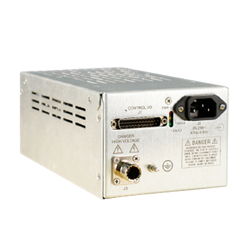
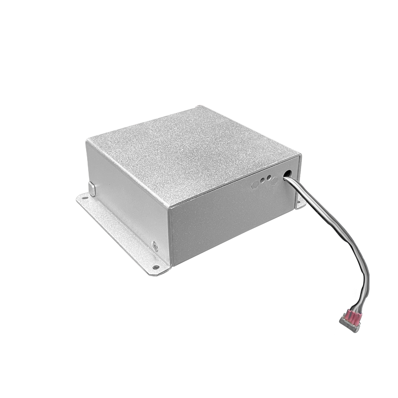
Mechanical structure design is strengthened to improve vibration and shock resistance: metal casings (e.g., aluminum alloy) enhance structural strength; internal components are fixed with bolts or potted (using epoxy resin potting adhesive with thermal conductivity ≥1.5W/m·K) to prevent component loosening due to vibration; structures meeting shock standards (e.g., MIL-STD-883H) are designed for application scenarios such as aerospace, withstanding 500g shock acceleration (lasting 1ms). In insulation design, multi-layer insulation structures (e.g., polyimide film + epoxy resin board) ensure insulation strength between high-voltage windings and the casing (withstand voltage ≥2 times the rated voltage); high-voltage connectors use sealed designs to prevent insulation degradation in humid environments.
(4) Testing and Verification
Comprehensive reliability tests are conducted before delivery, including environmental adaptability tests (high-temperature, low-temperature, humidity cycle, salt spray tests), mechanical performance tests (vibration, shock, drop tests), electrical performance tests (rated load, overload, short-circuit protection tests), and life tests (continuous operation under rated conditions for 5000 hours to monitor performance changes). Meanwhile, Failure Mode and Effects Analysis (FMEA) identifies potential failure modes (e.g., switching tube breakdown, capacitor aging), evaluates the severity of failure effects, and improves designs in advance (e.g., adding redundant switching tubes, selecting long-life capacitors). Through testing and verification, the failure rate of the power supply can be reduced to below 0.1 failures per 10,000 hours.
(5) Operation Monitoring and Maintenance Design
A condition monitoring module is integrated inside the power supply to collect real-time parameters such as output voltage, current, temperature, and humidity. Data is transmitted to the monitoring system via RS485 or Ethernet for remote condition monitoring; fault diagnosis functions are designed to indicate fault types (e.g., overvoltage, overcurrent, overtemperature) through indicator lights or displays, facilitating maintenance personnel to quickly locate faults. Meanwhile, modular design divides the power supply into independent units such as power modules, control modules, and heat dissipation modules, reducing the time to replace faulty modules to within 30 minutes and lowering maintenance costs.
3. Application Scenarios and Future Trends
Reliability assurance measures have been applied to high-voltage power supplies for medical MRI equipment (MTBF ≥150,000 hours, ensuring year-round trouble-free operation) and aerospace high-voltage power supplies (adapting to -55℃ to 125℃ temperature range, vibration resistance meeting MIL-STD-167). In the future, with the development of the Internet of Things and AI technology, high-voltage power supplies will realize predictive maintenance: AI algorithms analyze operating data to predict component aging trends (e.g., capacitor lifespan prediction error ≤5%), issuing maintenance warnings in advance; meanwhile, digital twin technology simulates the power supply's operating status under different conditions, optimizing maintenance strategies to further improve the reliability and service life of high-voltage power supplies.