Improvement of Output Voltage Dynamic Response Speed for High-Power Regulated Power Supplies
Introduction
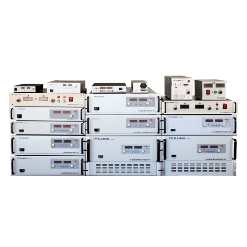
High-power regulated power supplies are key equipment in fields such as laser processing, medical imaging, and aerospace testing. In these applications, the load often changes suddenly (e.g., the laser power changes from low to high in an instant, or the medical imaging equipment switches working modes), which requires the power supply to adjust the output voltage quickly to suppress voltage overshoot or undershoot, ensuring the normal operation of the load. However, traditional high-power regulated power supplies have a slow dynamic response speed due to the large output filter capacitor, low control loop bandwidth, and slow switching speed of power devices, which cannot meet the requirements of fast-changing loads.
Core Technical Challenges
The main factors limiting the dynamic response speed include three aspects. First, the output filter capacitor has a large equivalent series resistance (ESR) and equivalent series inductance (ESL). When the load current changes suddenly, the voltage drop across ESR and ESL causes the output voltage to fluctuate, and the large capacitance value makes the capacitor charge and discharge slowly, prolonging the voltage recovery time. Second, the control loop bandwidth is low. The traditional proportional-integral (PI) controller has a narrow bandwidth to ensure system stability, which makes the loop unable to respond quickly to load changes. Third, the switching speed of power devices (such as insulated gate bipolar transistors (IGBTs)) is slow. The slow turn-on and turn-off speeds of IGBTs lead to large switching losses and slow adjustment of the output voltage, affecting the dynamic response.
Improvement Methods
Optimization of Output Filter Circuit
To reduce the impact of the output filter capacitor on dynamic response, a composite filter structure composed of low-ESR polymer capacitors and ceramic capacitors is adopted. The polymer capacitor has a large capacitance (e.g., 1000μF) and low ESR (less than 10mΩ), which can provide a large amount of charge quickly when the load current increases, reducing the voltage drop. The ceramic capacitor has a very low ESL (less than 1nH), which can suppress high-frequency voltage fluctuations caused by fast load current changes. The two types of capacitors are connected in parallel at the output end, with the ceramic capacitor close to the load to minimize the wiring inductance, further improving the high-frequency response performance.
In addition, a variable capacitance control strategy is introduced. The output filter circuit is equipped with multiple groups of polymer capacitors, and the control system adjusts the number of connected capacitors according to the load current change rate (di/dt). When the load current changes slowly (di/dt < 1A/μs), only a small number of capacitors are connected to reduce the equivalent capacitance and improve the dynamic response. When the load current changes rapidly (di/dt > 1A/μs), all capacitors are connected to provide sufficient charge and suppress voltage fluctuations. This strategy balances the requirements of voltage stability and dynamic response.
Enhancement of Control Loop Bandwidth
To improve the control loop bandwidth while ensuring system stability, a PID controller based on particle swarm optimization (PSO) is designed. The PSO algorithm is used to optimize the proportional gain (K_p), integral time constant (T_i), and derivative time constant (T_d) of the PID controller. The optimization objective is to maximize the loop bandwidth under the constraint that the overshoot is less than 5% and the settling time is less than 100μs.
First, the mathematical model of the high-power regulated power supply is established, including the power stage (inverter, rectifier), output filter, and load. Then, the PSO algorithm initializes a group of particles (each particle represents a set of PID parameters) and iteratively updates the particle positions according to the fitness function (comprehensive evaluation of bandwidth, overshoot, and settling time). After multiple iterations (e.g., 50 iterations), the optimal PID parameter combination is obtained.
In addition, a feedforward control loop is added to the PID control system. The feedforward controller samples the load current in real time and calculates the required control signal according to the transfer function of the power supply. This control signal is added to the output of the PID controller to adjust the power device in advance, reducing the lag of the feedback control. The feedforward coefficient is calibrated through experiments to ensure that the feedforward control can effectively compensate for the voltage drop caused by load current changes.
Adoption of High-Speed Power Devices
To improve the switching speed of power devices, gallium nitride (GaN) high-electron-mobility transistors (HEMTs) are used instead of traditional IGBTs. GaN HEMTs have a much higher switching speed (turn-on time < 10ns, turn-off time < 15ns) than IGBTs (turn-on time > 100ns, turn-off time > 150ns), which can significantly reduce the switching loss and improve the voltage adjustment speed.
In addition, the driving circuit of the GaN HEMT is optimized. A high-speed driver chip with a driving current of up to 10A is used to ensure that the GaN HEMT can be turned on and off quickly. The driving circuit also includes a gate voltage clamping circuit to prevent the gate voltage from exceeding the safe value, and a negative voltage turn-off circuit to reduce the turn-off time and avoid the shoot-through phenomenon.
Application Verification
A high-power regulated power supply (output voltage 0-1000V, rated current 500A) is modified using the above improvement methods, and its dynamic response performance is tested under different load conditions. The test results show that when the load current suddenly changes from 100A to 500A (di/dt = 2A/μs), the output voltage overshoot of the improved power supply is less than 3% (the traditional power supply is 10%-15%), and the voltage recovery time is 80μs (the traditional power supply is 500μs), which significantly improves the dynamic response speed.
In the laser cutting application test, the improved power supply is used to provide power for a high-power fiber laser (maximum power 10kW). During the laser cutting process, the laser power switches between 2kW and 10kW (corresponding to the load current changing between 100A and 500A) every 10ms. The test shows that the output voltage of the power supply remains stable within ±2V, and the laser cutting quality (cutting edge smoothness, cutting speed) is improved by 20% compared with the traditional power supply, which verifies the practical application effect of the improvement methods.
Conclusion
By optimizing the output filter circuit, enhancing the control loop bandwidth, and adopting high-speed power devices, the output voltage dynamic response speed of the high-power regulated power supply can be significantly improved. This meets the requirements of fast-changing loads in industrial and high-tech fields, and provides a reliable power guarantee for the development of high-performance equipment.
