Mechanical Shock Hardening Design for PPM-Level Precision High-Voltage Power Supplies
The demand for high-voltage power supplies with precision at the parts-per-million (PPM) level has extended from benign laboratory environments to harsh operational settings, including mobile military platforms, airborne radar systems, and oil-well logging equipment. After fifty years in this field, I can assert with certainty that achieving PPM stability in a laboratory is a significant challenge, but maintaining that stability under the duress of mechanical shock and vibration is an entirely different discipline. It requires a fundamental shift in design philosophy, treating the mechanical structure not as a mere enclosure, but as an integral component of the electrical circuit's stability.
The core of the problem lies in the parasitic reactances within the high-voltage section. At PPM levels of precision, even the slightest geometric distortion of a high-voltage electrode or a change in the spacing between components can alter the stray capacitance by a few femtofarads. While seemingly negligible, this minute capacitance change, when coupled with the high-frequency ripple currents present in a switching power supply, can induce a voltage variation that pushes the output outside the PPM stability window. A shock event can cause a momentary micro-bending of a support insulator or a slight compression of a shielding can, leading to a transient in the output voltage that takes milliseconds or even seconds to settle, rendering the equipment useless during that critical period.
Therefore, the design process must begin with a comprehensive modal analysis of the entire power assembly. Finite element analysis is not an optional extra but a mandatory first step. The objective is to identify and eliminate resonant frequencies that coincide with the expected shock spectrum. All internal components, from the largest transformer to the smallest surface-mount resistor, must be considered. The high-voltage multiplier stack, often a series of diodes and capacitors, is particularly vulnerable. If this assembly is not rigidly constrained, a shock can cause the individual stages to vibrate against one another, leading not only to electrical noise but also to catastrophic mechanical failure. The solution often involves full encapsulation with a high-durometer, thermally conductive epoxy. This transforms a collection of discrete components into a single, monolithic block with a high natural frequency, far above the energy-rich region of most shock events.
The design of the high-voltage transformer itself requires special attention. The windings, especially the secondary, are massive copper structures. Under shock, these windings can experience tremendous g-forces, causing them to shift. This movement alters the leakage inductance and inter-winding capacitance. In a PPM supply, which often relies on a resonant converter topology for soft switching, a change in leakage inductance can detune the resonant tank, causing a loss of zero-voltage switching and a subsequent burst of electromagnetic interference that contaminates the output. Potting the transformer in a void-free medium under vacuum is essential. Furthermore, the core material must be clamped with a pre-load force significantly higher than the peak force expected during shock to prevent any magnetostrictive or inertial movement.
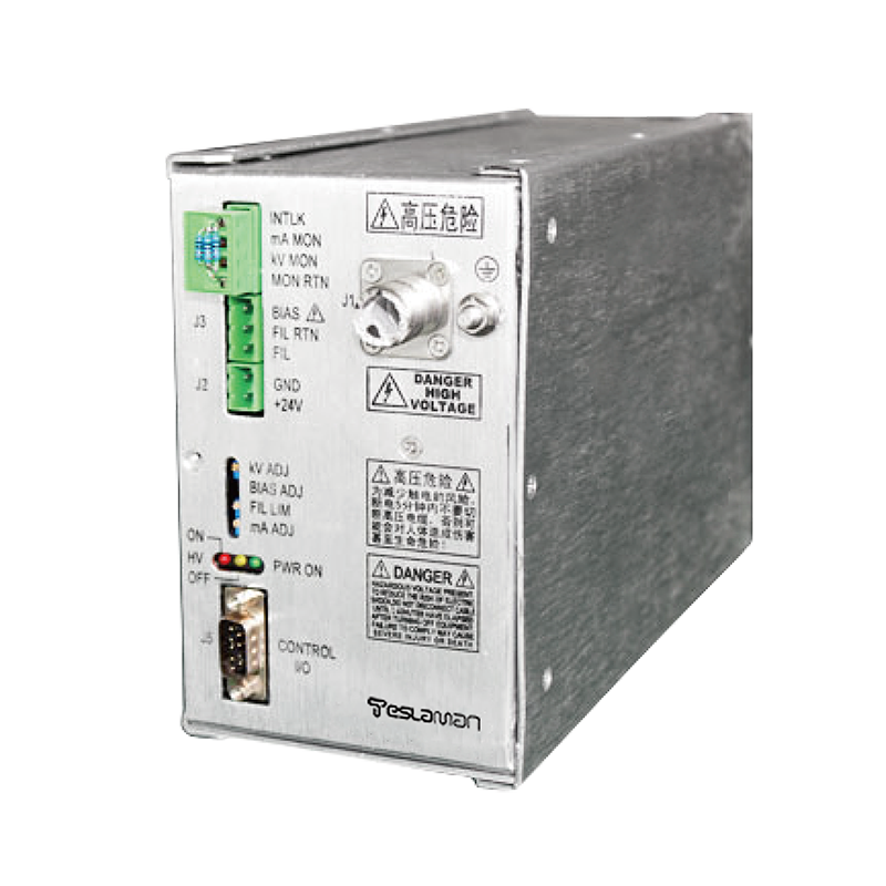
Connectors and cabling represent the weakest link in the mechanical chain. A standard high-voltage connector, when subjected to a shock, can experience a momentary micro-disconnection at the pin-socket interface. For a PPM-level system, this micro-disconnection manifests as a sudden, uncontrolled arc or a high-impedance state that corrupts the feedback signal. The solution is to use specialised, ruggedised connectors with multiple independent contact points and a positive locking mechanism that exerts a constant high force on the mating surfaces. Alternatively, hard-wired connections with strain-relief loops potted in place are often more reliable. The feedback divider, typically a precision resistive chain, must be mounted in a stress-isolated manner. Even microscopic strain on the resistor bodies or their solder joints can induce the piezo-resistive effect, causing a temporary change in resistance that mimics a true output voltage change, leading the control loop astray. Isolating these sensitive components on damped sub-assemblies or using foil-based resistors, which are less sensitive to strain, is a common hardening technique.
Ultimately, the validation of a PPM power supply for shock requires a test regime that goes beyond standard military specifications. It is not enough to simply check for functionality before and after a shock. The output voltage must be monitored in real-time during the shock event with nanovolt sensitivity. This requires a measurement system isolated from the mechanical shock itself, often using fibre-optic links to transmit the analogue signal from the vibrating unit under test to a stationary digitiser. Only through such rigorous testing can we guarantee that the supply will maintain its PPM-level precision when it is most needed, proving that the marriage of high-voltage electrical engineering and precision mechanical design has been successfully consummated.