Lifetime Prediction of High Voltage Strobe Power Supply for High-speed Ampoule Visual Inspection System
High-speed visual inspection systems for pharmaceutical ampoules require intense, precisely timed illumination to capture clear images of the contents for defect detection. High voltage strobe power supplies provide the energy for xenon flash lamps that generate the illumination pulses. Predicting the lifetime of these power supplies is essential for maintenance planning and ensuring continuous operation of the inspection system.
The visual inspection process for ampoules involves capturing images as the containers move rapidly past inspection stations. The illumination must be bright enough to reveal defects such as particles, cracks, or improper filling. The flash duration must be short enough to freeze the motion of the moving containers. The flash repetition rate must match the throughput of the inspection line, which may be hundreds of containers per minute. These requirements place demanding specifications on the strobe power supply.
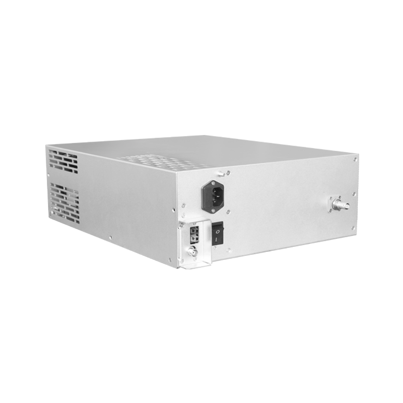
The high voltage strobe power supply stores energy in a capacitor and discharges it through the flash lamp when triggered. The capacitor is charged to several hundred volts through a charging circuit. When the trigger signal arrives, an ignition circuit creates a high voltage pulse that ionizes the gas in the flash lamp. The main capacitor then discharges through the ionized gas, producing an intense flash of light. The flash duration is determined by the capacitor value and the lamp characteristics.
The lifetime of a strobe power supply is limited by several degradation mechanisms. The flash lamp electrodes erode with each discharge, gradually increasing the trigger voltage requirement and reducing the light output. The capacitor degrades with repeated charge-discharge cycles, losing capacitance and increasing equivalent series resistance. The charging circuit components experience thermal and electrical stress that can cause gradual degradation. The trigger circuit components may degrade from the high voltage pulses.
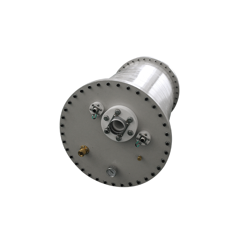
Flash lamp lifetime is typically specified by the manufacturer in terms of the number of flashes to a certain percentage of initial light output. The lifetime depends on the energy per flash, the flash duration, and the cooling conditions. Higher energy flashes cause more electrode erosion and faster degradation. The lifetime specification provides a baseline for maintenance planning, but actual lifetime can vary significantly depending on operating conditions.
Capacitor lifetime depends on the operating conditions and the capacitor technology. Electrolytic capacitors have limited lifetime due to electrolyte degradation, typically specified in hours of operation at rated temperature and voltage. Film capacitors have longer lifetime but may still degrade due to dielectric stress. The lifetime accelerates with temperature, with typical rules specifying doubling of degradation rate for each ten degree temperature increase. The capacitor lifetime often determines the overall power supply lifetime.
Thermal management significantly affects the lifetime of power supply components. The charging circuit generates heat during operation, particularly at high repetition rates. The flash lamp generates heat during each discharge. The power supply enclosure must provide adequate cooling to maintain component temperatures within acceptable limits. Active cooling with fans or liquid cooling may be required for high-power applications.
Lifetime prediction models combine the degradation rates of individual components to estimate the overall system lifetime. Statistical models based on historical failure data can predict the probability of failure as a function of operating time and conditions. Physics-based models use the known degradation mechanisms to predict the remaining useful life. Hybrid approaches combine statistical and physics-based models for improved accuracy.
Condition monitoring enables real-time assessment of power supply health. Measurements of the flash energy, trigger voltage, and charging time can indicate the degradation state of critical components. Temperature monitoring can detect thermal problems before they cause failures. Trend analysis of these parameters can predict when maintenance will be required. Integration with the inspection system control enables automatic alerts when maintenance is needed.
Accelerated life testing provides data for lifetime prediction models. Power supplies are operated under elevated stress conditions such as higher temperature or higher repetition rate to accelerate the degradation processes. The failure times under accelerated conditions are extrapolated to predict the lifetime under normal operating conditions. The acceleration factors must be carefully determined to ensure accurate predictions.
Maintenance strategies based on lifetime prediction can optimize the balance between reliability and cost. Preventive maintenance replaces components before they fail, avoiding unplanned downtime. Predictive maintenance uses condition monitoring to schedule maintenance when degradation indicates that failure is approaching. Run-to-failure maintenance accepts occasional failures when the consequences are manageable. The appropriate strategy depends on the criticality of the inspection system and the cost of downtime.