Simulation of Electric Field Distribution of Colored Fibers in Multi-color Three-dimensional Electrostatic Flocking High Voltage Power Supply
Electrostatic flocking is a coating process that applies short fibers to an adhesive-coated substrate using electrostatic forces. Multi-color three-dimensional flocking creates decorative and functional surfaces with patterns of different colored fibers standing at various angles. The high voltage power supply creates the electric field that orients and drives the fibers toward the substrate. Simulation of the electric field distribution enables optimization of the flocking process for achieving desired fiber orientation and color patterns.
The electrostatic flocking process begins with the application of adhesive to the substrate surface. Short fibers, typically a fraction of a millimeter in length, are then introduced into an electric field between a high voltage electrode and the grounded substrate. The fibers become charged and align with the electric field lines, accelerating toward the adhesive-coated surface. Upon contact with the adhesive, the fibers become embedded and remain standing perpendicular to the surface.
Multi-color flocking requires the sequential or simultaneous application of fibers of different colors. The fibers must be directed to specific areas of the substrate to create the desired color pattern. The electric field distribution determines where fibers of each color will deposit. Controlling the field distribution enables creation of complex multi-color patterns.
Three-dimensional flocking creates surfaces with fibers standing at various angles rather than uniformly perpendicular. The fiber orientation affects the visual appearance and the tactile properties of the flocked surface. The electric field direction at the substrate surface determines the fiber orientation. Controlling the field direction enables creation of three-dimensional textures.
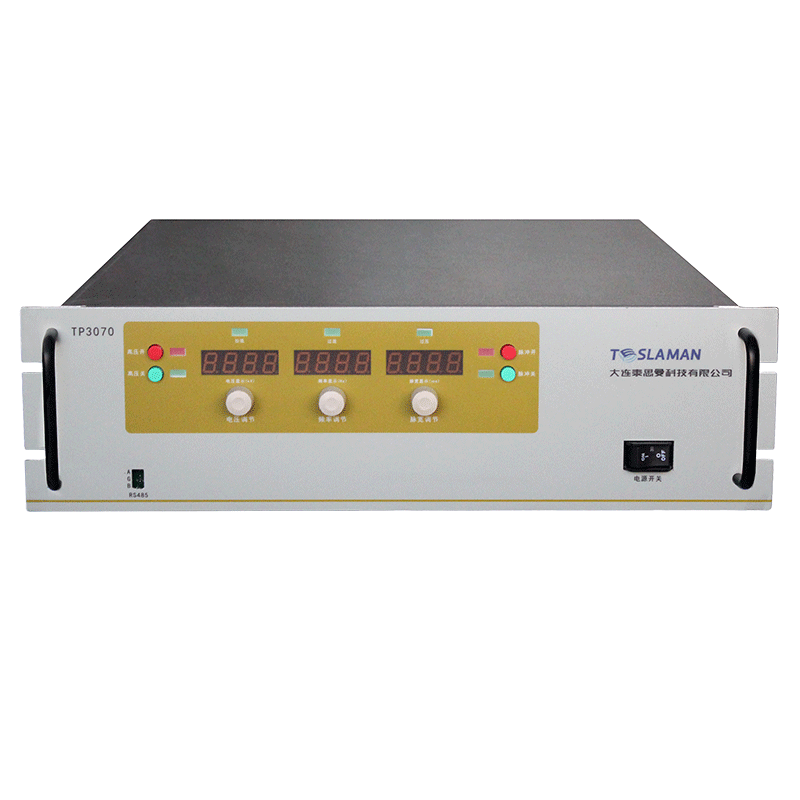
The high voltage power supply provides the voltage that creates the electric field. Typical flocking voltages range from tens to hundreds of kilovolts, depending on the fiber length, the electrode configuration, and the desired fiber density. The power supply must provide stable voltage to maintain consistent field conditions during the flocking process.
Electric field simulation uses computational methods to model the field distribution in the flocking apparatus. Finite element analysis divides the geometry into small elements and solves the electrostatic equations for each element. The simulation predicts the field strength and direction at every point in the flocking zone. This information guides the design of the electrode configuration and the selection of operating parameters.
The electrode configuration significantly affects the field distribution. Plate electrodes create relatively uniform fields suitable for uniform flocking. Point or wire electrodes create non-uniform fields that can direct fibers to specific areas. Multiple electrodes can create complex field patterns for multi-color or three-dimensional flocking. The simulation enables optimization of the electrode geometry for the desired flocking pattern.
The substrate geometry affects the field distribution near the surface. Curved or contoured substrates distort the field lines, affecting the fiber orientation. The simulation can model the substrate geometry and predict the resulting field distribution. This enables design of electrode configurations that compensate for substrate geometry effects.
Colored fibers may have different electrical properties depending on the fiber material and the dye or pigment used. Different fiber types may charge differently in the electric field, affecting their trajectory and deposition. The simulation can incorporate the electrical properties of different fiber types to predict their behavior. This enables optimization of the process parameters for each fiber type.
The adhesive layer on the substrate affects the field distribution. The adhesive is typically a dielectric material that modifies the field near the substrate surface. The adhesive thickness and dielectric constant affect the field strength at the fiber landing point. The simulation can model the adhesive layer and predict its effect on the flocking process.
Process parameters including the voltage level, the electrode spacing, and the fiber feed rate affect the flocking results. Higher voltages create stronger fields that drive fibers more forcefully toward the substrate. The electrode spacing affects the field uniformity and the fiber acceleration distance. The fiber feed rate affects the fiber density and the uniformity of coverage. The simulation can predict the effects of parameter variations, guiding process optimization.
Validation of simulation results requires comparison with experimental flocking results. Test flocked samples can be analyzed to determine fiber orientation, density, and pattern accuracy. Comparison of measured results with simulation predictions validates the model and identifies areas for improvement. Iterative refinement of the simulation model improves its predictive accuracy.
Integration of simulation with process control enables real-time optimization. The simulation can be used to generate lookup tables or response surface models that relate electrode configuration and process parameters to flocking outcomes. The process control system can use these models to automatically adjust parameters for different substrate geometries or flocking patterns. This enables efficient production of diverse flocking products with consistent quality.