Modular Design and Hot Swap Maintenance Convenience of Standard Rack Mounted High Voltage Power Supply
Standard rack mounted high voltage power supplies have become the preferred form factor for many industrial and scientific applications. The modular design enables configuration flexibility, scalability, and convenient maintenance. Hot swap capability allows modules to be replaced without powering down the entire system, maximizing uptime and simplifying maintenance procedures.
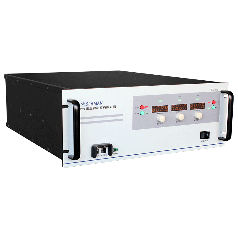
Rack mounted equipment follows standard dimensions defined by the Electronic Industries Alliance. The standard rack width is nineteen inches, and the height is specified in units of one point seven five inches. This standardization enables equipment from different manufacturers to be installed in the same rack enclosure. High voltage power supplies are available in various rack heights depending on their power and voltage ratings.
Modular design divides the power supply functionality into discrete modules that can be independently installed, configured, and serviced. Common module types include power modules that perform the voltage conversion, control modules that manage the operation, and interface modules that provide communication and user interface functions. The modular approach offers several advantages over monolithic designs.
Configuration flexibility enables the power supply system to be tailored to the application requirements. The number of power modules determines the total power capability. Multiple modules can be connected in parallel for higher current, in series for higher voltage, or operated independently for multiple output channels. The user can configure the system by installing the appropriate modules in the available slots.
Scalability enables the system to grow with changing requirements. Additional power modules can be added to increase capability without replacing the entire system. The modular architecture supports this expansion by providing the infrastructure for additional modules. The control system must accommodate the expanded configuration, typically through software configuration rather than hardware changes.
Fault isolation is simplified with modular design. When a fault occurs, the system can identify which module is affected. This localization speeds troubleshooting and repair. The faulty module can be replaced while other modules continue operating. The system may be able to operate at reduced capacity with fewer modules, maintaining partial functionality during repair.
Hot swap capability allows modules to be removed and inserted while the system is operating. This capability requires careful electrical and mechanical design to ensure safe and reliable operation during the swap. The system must detect the module removal and insertion, reconfigure appropriately, and prevent electrical transients that could cause damage.
Electrical design for hot swap includes several considerations. The module connector must be designed to make and break connections in a controlled sequence. Typically, ground connections are made first and broken last to prevent floating voltages. Power connections may be staggered to control the inrush current when a module is inserted. Soft start circuits limit the current surge as the module capacitors charge.
The system must detect module insertion and removal. Mechanical switches or electrical sensing circuits detect when a module is present. The control system monitors these signals and responds appropriately. When a module is removed, the control system may redistribute load to remaining modules or issue an alarm. When a module is inserted, the control system identifies the module type and incorporates it into the system configuration.
Module identification enables the system to recognize different module types and configure appropriately. Electronic identification devices store module parameters such as type, serial number, and calibration data. The system reads this information when the module is inserted and uses it for configuration and diagnostics. This automatic identification eliminates manual configuration and reduces the chance of errors.
Mechanical design for hot swap includes the module guide rails, connectors, and latching mechanisms. The guides ensure proper alignment as the module is inserted. The connector must tolerate the insertion cycles without degradation. The latch secures the module in place and may provide indication that the module is fully seated. The mechanical design must provide adequate cooling airflow to the module.
Maintenance convenience extends beyond hot swap to include other features that simplify service. Front panel indicators show module status, enabling quick identification of faulty modules. Test points provide access to key signals for troubleshooting. Module extraction handles allow easy removal without tools. These features reduce the time and skill required for maintenance, lowering the total cost of ownership.