Synchronous Triggering Precision Analysis of Modular High Voltage Pulsed Power Supply for Electromagnetic Forming
Electromagnetic forming utilizes the magnetic pressure generated by high current pulses to shape conductive materials at high velocity, enabling forming operations that are difficult or impossible with conventional mechanical methods. The process involves discharging high voltage capacitors through a coil positioned near the workpiece, generating intense magnetic fields that induce currents in the conductive workpiece. The interaction between the coil current and the induced workpiece current produces magnetic pressure that accelerates the workpiece toward a die or into free space. Modular high voltage pulsed power supplies enable scaling to higher energies and provide flexibility for different forming configurations. The synchronous triggering of multiple modules determines the current waveform characteristics and the forming effectiveness, with triggering precision being critical for achieving coordinated discharge from all modules.
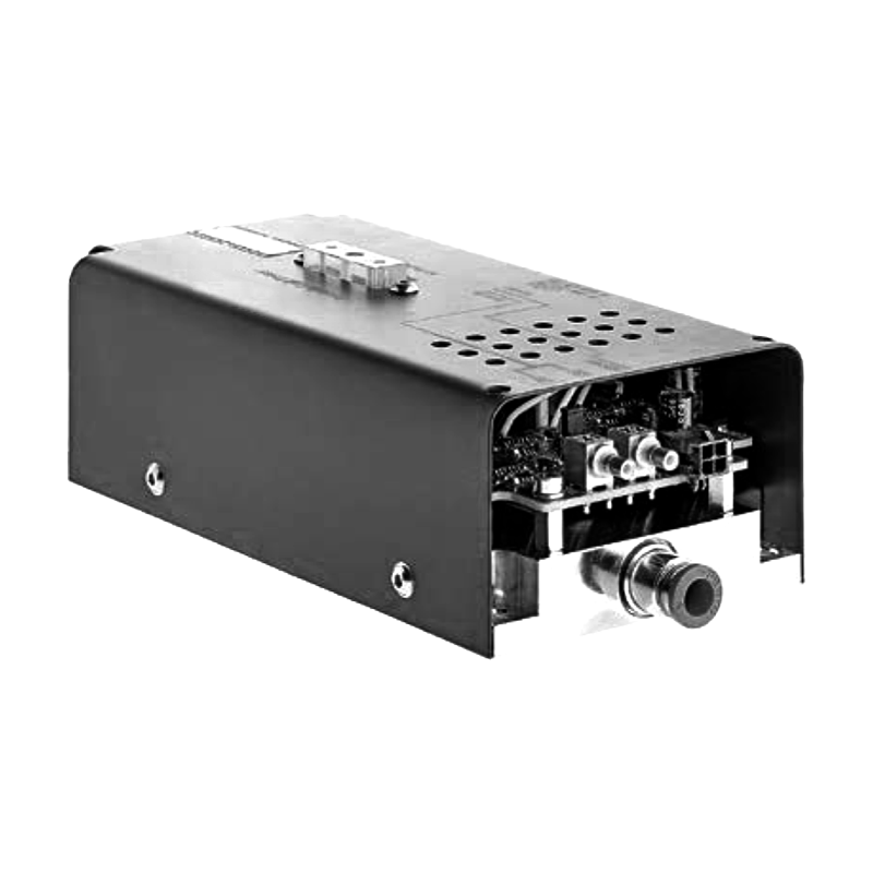
Modular pulsed power architectures divide the total energy storage and switching capability among multiple units that can be combined to achieve higher performance than practical with single units. Each module contains energy storage capacitors, switching devices, and local control circuits. The modules are connected in parallel to combine their currents at the load, or in series to combine their voltages. The modular approach provides redundancy, scalability, and the ability to optimize each module for its specific role in the system.
Synchronous triggering requires that all modules initiate their discharge within a narrow time window relative to the overall pulse duration. If modules trigger at significantly different times, the current waveform becomes distorted and the magnetic pressure profile deviates from the intended shape. Early triggering modules may experience higher initial current as they discharge into the load before other modules contribute. Late triggering modules may contribute after the forming process has already begun or completed, reducing their effectiveness.
The required triggering precision depends on the pulse duration and the sensitivity of the forming process to timing variations. Electromagnetic forming pulses typically have durations in the tens to hundreds of microseconds, with the forming action occurring during the first quarter cycle of the oscillating discharge. Triggering jitter should be a small fraction of this characteristic time, typically requiring precision of microseconds or better. For very fast forming processes with shorter pulses, the precision requirements become more demanding.
Triggering jitter arises from several sources including variations in the trigger signal propagation, differences in the response times of individual modules, and statistical variations in the switching device turn on. The trigger signal distribution system must deliver the trigger command to all modules with minimal variation in propagation delay. Equal length cables or matched transmission line structures ensure that the trigger signal arrives at all modules simultaneously.
The trigger receiver circuits in each module convert the trigger signal to the gate drive for the switching devices. Variations in the receiver threshold, response time, and output drive affect the timing consistency between modules. Careful design of these circuits with appropriate bandwidth, threshold precision, and drive capability minimizes the contribution to triggering jitter. Temperature variations can affect the circuit characteristics, requiring temperature compensation or stable thermal environments.
The switching devices themselves introduce timing variations. Thyristors and spark gaps have statistical turn on characteristics that vary from pulse to pulse. The turn on delay depends on the gate drive amplitude, the anode voltage, and the device temperature. Operating conditions that minimize the turn on delay and its variation improve the triggering precision. Using devices with matched characteristics or selecting devices from the same manufacturing lot can reduce the device to device variation.
Optical triggering provides excellent isolation and precise timing for high voltage modules. Optical fibers transmit trigger signals from a central controller to each module without electrical connections that could carry interference or create ground loops. The optical receivers convert the light signal to electrical triggers with high bandwidth and low jitter. The optical approach is particularly advantageous for modules at different high voltage potentials where electrical triggering would require isolation.
Triggering sequence and timing may need to be adjusted for different forming configurations. Some applications benefit from staggered triggering that shapes the current waveform profile. Pre triggering of certain modules can establish initial conditions before the main discharge. The triggering system should provide the flexibility to program different timing sequences while maintaining the precision for synchronous operation.
Monitoring of the actual triggering timing enables detection of problems and verification of system performance. Current sensors or voltage probes on each module capture the discharge initiation time. Comparison of the timing across modules reveals any jitter or systematic timing differences. This monitoring data supports maintenance of the triggering system and identification of modules that may require adjustment or replacement.
Fault conditions in one module should not prevent other modules from triggering or cause unsafe operation. The triggering system should detect faults such as failure to trigger or premature triggering and initiate appropriate protective actions. Interlock logic should prevent triggering if conditions are not safe for discharge, such as insufficient charging voltage or faults in the load circuit.
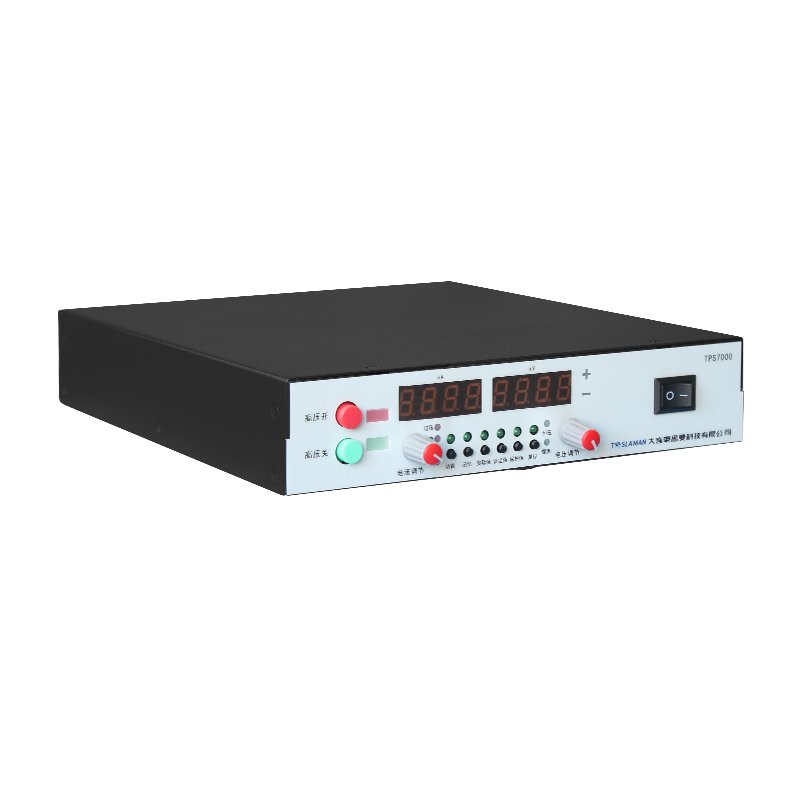
The high voltage charging system that energizes the module capacitors must complete charging before the trigger command is issued. The charging time depends on the energy storage capacity, the charging power, and the target voltage. The control system must coordinate the charging and triggering sequences, allowing adequate time for charging while minimizing the overall cycle time for production forming operations.