Nonlinear Distortion Compensation Algorithm of Beam Scanning High Voltage Deflection Power Supply for Ion Implanter
Ion implanters inject ions into semiconductor wafers to modify electrical properties, creating doped regions for transistors and other devices. Beam scanning systems distribute the ion beam across the wafer surface, ensuring uniform implantation. High voltage deflection power supplies control the beam scanning by applying voltages to deflection electrodes that steer the beam. Nonlinear distortion in the scanning pattern causes implantation nonuniformity, requiring compensation algorithms to correct the distortion and achieve uniform implantation.
Ion implantation accelerates ions to high energy and directs them at the wafer surface. The ions penetrate the wafer, creating doped regions with depths determined by the ion energy and concentrations determined by the ion dose. Uniform implantation across the wafer requires uniform beam exposure at all locations. The beam scanning system distributes the beam across the wafer, compensating for the beam profile and the wafer geometry.
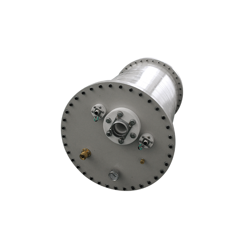
Electrostatic beam scanning uses deflection electrodes that create electric fields perpendicular to the beam direction. The fields deflect the beam, changing its trajectory and directing it to different wafer locations. Varying the deflection voltage scans the beam across the wafer in a controlled pattern. The scanning pattern must cover all wafer locations with appropriate dwell times to achieve uniform dose.
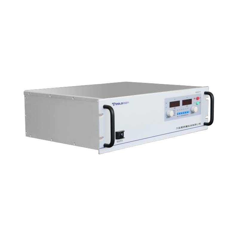
The high voltage deflection power supply provides the voltages for the deflection electrodes. The voltage range determines the deflection range, with higher voltages providing larger deflection angles. The voltage precision determines the beam position precision. The voltage speed determines the scanning speed. The power supply must provide precise, fast, stable voltage for accurate beam scanning.
Nonlinear distortion in beam scanning arises from several sources. The deflection sensitivity, the beam deflection per unit voltage, may vary across the deflection range. The electrostatic field geometry may cause nonuniform deflection characteristics. The beam optics may introduce aberrations that affect the beam position. The mechanical alignment of components may cause position errors. The combined effects create nonlinear relationship between voltage and beam position.
Distortion effects on implantation uniformity cause dose variations across the wafer. If the beam spends more time at some locations due to scanning distortion, those locations receive higher dose. If the beam spends less time at other locations, those locations receive lower dose. The dose nonuniformity affects device characteristics, potentially causing performance variations or yield loss.
Compensation algorithms correct the nonlinear distortion by adjusting the scanning pattern. The algorithms modify the deflection voltages to counteract the distortion, achieving uniform beam coverage. The compensation requires knowledge of the distortion characteristics, either from theoretical models or from empirical measurements. The algorithms apply corrections based on the known distortion.
Calibration measurement determines the actual beam position versus the commanded deflection voltage. Beam position sensors measure the beam location at various voltage settings, mapping the voltage to position relationship. The measurement reveals the nonlinear distortion present in the scanning system. The calibration data provide the basis for compensation.
Lookup table compensation uses stored correction values for each scanning position. The lookup table contains the corrected voltage needed to achieve each desired beam position. During scanning, the system retrieves the corrected voltage from the table and applies it to the deflection electrodes. The lookup table directly implements the measured correction without requiring calculation.
Polynomial compensation uses mathematical functions to calculate corrections. The distortion characteristics are fitted to polynomial functions that describe the voltage to position relationship. During scanning, the functions calculate the corrected voltage needed for each desired position. Polynomial compensation provides smooth correction without the discrete steps of lookup tables.
Real time compensation adjusts the correction based on current conditions. The distortion may vary with beam parameters, temperature, or other factors. Real time measurement of beam position enables continuous correction adjustment, maintaining accuracy despite changing conditions. Real time compensation requires position measurement during implantation, which may be challenging.
Two dimensional scanning uses two deflection systems, typically horizontal and vertical, to scan the beam across the wafer in both dimensions. Each dimension may have its own distortion characteristics requiring separate compensation. The interaction between the two dimensions may create additional distortion requiring combined compensation. The two dimensional compensation must correct both dimensions and their interactions.
Dwell time compensation adjusts the time spent at each position to achieve uniform dose. Even with position correction, the beam velocity may vary across the scan pattern, causing dose variations. Dwell time compensation adjusts the scanning speed or the dwell time at each position to equalize the dose. The combined position and dwell time compensation achieves uniform implantation.
Verification of compensation effectiveness measures the implantation uniformity across the wafer. Test implants with uniform target dose are measured at multiple wafer locations, revealing the actual dose distribution. The uniformity metrics quantify the dose variation. The verification confirms that the compensation achieves the required uniformity for device fabrication.