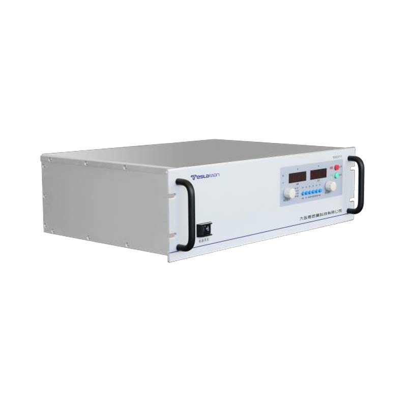
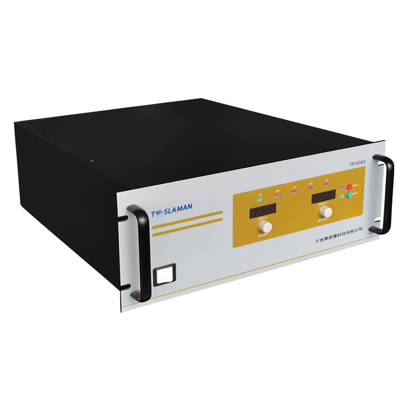
Magnetron Sputtering Vacuum Coating High Voltage Power Supply Power Factor Correction
The magnetron sputtering process is widely used for depositing thin films of metals, oxides, and other materials in applications ranging from semiconductor manufacturing to architectural glass coating. The high voltage power supply that drives the magnetron discharge is a critical component that directly influences the deposition rate, film quality, and process stability. Power factor correction has become an increasingly important aspect of these power supply designs as manufacturers seek to improve energy efficiency, reduce operating costs, and comply with stringent power quality regulations. The nonlinear nature of the magnetron load presents unique challenges for power factor correction that require careful engineering solutions.
A typical magnetron sputtering power supply operates with an output voltage of 300 V to 1000 V and output currents ranging from 1 A to 100 A or more, depending on the target size and material. The input stage of the power supply converts the three-phase AC mains voltage to a regulated DC bus voltage that feeds the output inverter stage. Without power factor correction, the input rectifier and filter capacitor circuit draws current in short pulses near the peak of the AC voltage waveform, resulting in a high total harmonic distortion and a poor power factor, typically in the range of 0.6 to 0.7. This low power factor increases the RMS current drawn from the mains, leading to higher losses in the distribution system and reduced capacity utilization.
The power factor correction circuit in a magnetron sputtering power supply is typically implemented as a boost converter operating in continuous conduction mode. The boost converter shapes the input current waveform to follow the sinusoidal shape of the input voltage, achieving a power factor close to unity. The control circuit for the boost converter senses the input voltage and current and adjusts the switching duty cycle to maintain a sinusoidal input current waveform. The output of the boost converter is a regulated DC bus voltage, typically 650 V to 800 V for a three-phase input, which provides a stable input to the output inverter stage.
The design of the power factor correction circuit must account for the specific requirements of the magnetron sputtering application. The sputtering process can exhibit sudden changes in load impedance as the plasma conditions change, particularly during the transition from the glow discharge to the arc discharge regime. The power factor correction circuit must maintain stable operation during these transient events without tripping the overcurrent protection or causing excessive voltage ripple on the DC bus. The control loop bandwidth of the power factor correction circuit is typically limited to a few hundred hertz to ensure stability, which means that the DC bus capacitance must be sufficient to absorb the transient energy from load changes.
Interleaved boost converter topologies offer significant advantages for power factor correction in high-power magnetron sputtering applications. By operating two or more boost converters in parallel with phase-shifted switching signals, the input current ripple is reduced and the effective switching frequency is multiplied. This reduces the size of the input electromagnetic interference filter and the boost inductor, while also improving the transient response. The interleaved approach also provides redundancy, as the system can continue to operate at reduced power if one of the boost stages fails.
Three-level power factor correction topologies have gained popularity for higher voltage applications. The three-level boost converter uses two switching devices and two diodes to generate three voltage levels at the switching node, reducing the voltage stress on the switching devices and allowing the use of devices with lower voltage ratings. The reduced voltage stress also enables higher switching frequencies, which further reduces the size of magnetic components. The three-level topology is particularly well-suited for silicon carbide switching devices, which can operate at higher voltages and frequencies than silicon devices.
The control algorithm for the power factor correction circuit must coordinate with the output inverter control to ensure stable operation of the sputtering process. The DC bus voltage is regulated by the power factor correction circuit, while the output voltage and current are regulated by the inverter stage. The inverter control loop must be designed to appear as a constant power load to the power factor correction circuit, preventing interaction between the two control loops. Feedforward compensation from the DC bus voltage to the inverter duty cycle can improve the transient response and reduce the DC bus capacitance requirement.
Electromagnetic compatibility is a major consideration in the design of power factor correction circuits for magnetron sputtering power supplies. The switching action of the boost converter generates electromagnetic interference at the switching frequency and its harmonics. The input filter must attenuate this interference to meet the applicable electromagnetic compatibility standards, such as EN 55011 for industrial equipment. The filter design must balance the requirements for interference attenuation with the need for low leakage current and small physical size. Common mode chokes, differential mode inductors, and X and Y capacitors are used in combination to achieve the required attenuation.
The efficiency of the power factor correction circuit directly impacts the overall efficiency of the sputtering power supply. Modern power factor correction circuits using silicon carbide switching devices can achieve efficiencies exceeding 98 percent at full load. The losses in the boost inductor, switching devices, and diodes must be carefully managed through proper magnetic design and thermal management. The inductor core material is selected to minimize core losses at the switching frequency, while the winding design minimizes skin and proximity effects. The switching devices are mounted on heatsinks with adequate thermal capacity to maintain junction temperatures within safe limits.
Monitoring and diagnostics features in modern power factor correction circuits provide valuable information for preventive maintenance and troubleshooting. The power factor, total harmonic distortion, input voltage, and input current are continuously monitored and displayed on the power supply user interface. The system can log historical data and generate alarms when the power factor or harmonic distortion exceeds preset thresholds. This information helps operators identify potential problems with the power supply or the mains distribution system before they lead to process interruptions.
The integration of power factor correction into magnetron sputtering power supplies has become standard practice in modern systems. Regulatory requirements such as the European Union Electromagnetic Compatibility Directive and the International Electrotechnical Commission standard 61000-3-12 impose limits on harmonic current emissions from equipment with input currents above 16 A per phase. Compliance with these standards requires active power factor correction for most sputtering power supplies above 5 kW output power. The additional cost of the power factor correction circuit is offset by the energy savings, reduced installation costs, and improved process stability that result from the higher power quality.
Advanced power factor correction techniques continue to evolve, driven by the development of new semiconductor devices and control algorithms. The use of silicon carbide and gallium nitride devices enables higher switching frequencies and lower losses, leading to more compact and efficient power factor correction circuits. Digital control implementations using field-programmable gate arrays and digital signal processors allow more sophisticated control algorithms that can adapt to changing load conditions and optimize the power factor correction performance in real time. These advances will continue to improve the efficiency and reliability of magnetron sputtering power supplies, supporting the ongoing development of thin film deposition technology.