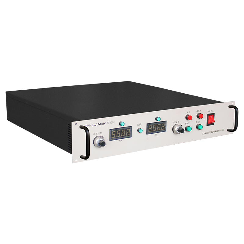
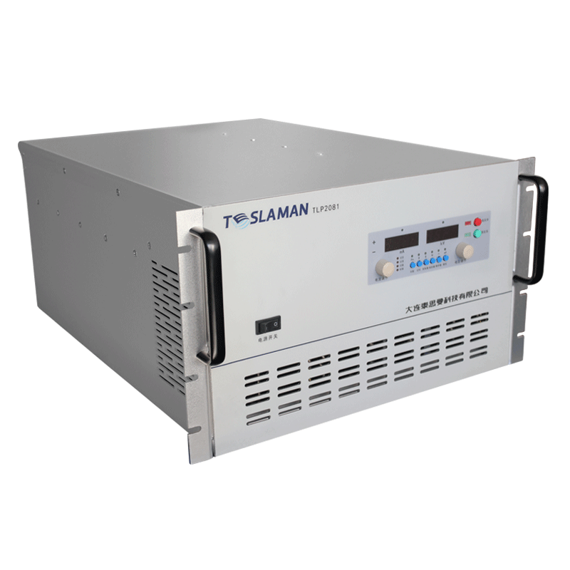
Uniformity Assurance of Vacuum Coating High-Voltage Supply in Optical Lens and Anti-Fog Coating Preparation
Vacuum coating supplies for optical lens and anti-fog coatings must deliver a stable deposition power across the full surface of the lens. The coating uniformity depends on the plasma density distribution, and the plasma density is governed by the power delivered by the supply. The uniformity assurance starts with the power accuracy and extends to the process coordination.
The deposition power is held constant by a power loop that multiplies the measured voltage and current. The loop corrects the output as the plasma impedance drifts during the deposition, and the correction speed is matched to the impedance drift rate. The power accuracy is verified with a calibrated power meter.
Anti-fog coatings are typically deposited as thin layers on curved surfaces, and the layer thickness controls the wetting behavior. A thickness error shifts the performance of the coating, so the deposition rate must remain stable throughout the batch. The rate stability is tied to the power stability of the supply.
Multi-layer optical coatings require a defined sequence of layers with different materials. Each layer is deposited at a specific power level, and the transition between layers must be clean. The supply switches the power level under recipe control, and the transition is verified to be free of overshoot.
The reactive deposition processes are sensitive to the target condition. A target poisoning event changes the discharge impedance and the deposition chemistry, and the supply must detect the change and adjust the operating point. The detection logic uses the voltage-current characteristic of the discharge.
Arc events disturb the deposition and create defects in the layer. The arc detection circuit shuts the output within microseconds, and the recovery sequence restarts the discharge after a defined delay. The arc count is logged and used to schedule the target maintenance.
Batch-to-batch repeatability requires that the supply behavior remains identical over time. The recipe parameters are stored in a protected memory, and the calibration records show the drift of the power accuracy. A drift beyond the tolerance triggers a recalibration.
The maintenance of the supply covers the power stage, the sampling chain, and the cooling system. The sampling chain is the accuracy-critical part, and the calibration interval follows the quality system of the coating line.
Quality records link the equipment performance to the product quality. The operating parameters and the product measurements are filed together, so that a product deviation can be traced to the equipment condition. The record retention period follows the regulatory and contractual requirements.
Vendor coordination covers the technical support, the spare supply, and the repair service. The service level agreement defines the response time and the repair turnaround. The vendor performance is reviewed periodically, and the review outcome influences the future procurement decisions.
Continuous improvement is driven by the analysis of the failure data and the operating experience. Each improvement proposal is assessed for the benefit, the cost, and the risk before implementation. The implemented improvements are tracked for the realized benefit.
Operator handover between shifts includes the equipment status, the pending issues, and the instructions for the current operation. The handover log is signed by both parties, and the entries are concise and factual. The handover discipline maintains the continuity of the operation.
Performance monitoring covers the key parameters that indicate the health of the supply. The monitoring points and the thresholds are defined during commissioning, and the measured values are recorded on a regular basis. The monitoring data support the early detection of the degradation trends.
Long-term stability of the supply is verified by the periodic re-measurement of the output characteristics. The measurements are compared with the baseline recorded at acceptance, and the drift trend is analyzed. A drift beyond the tolerance triggers a detailed investigation and a corrective action.
Troubleshooting flow guides the maintenance crew from the symptom to the probable cause. The flow is built from the documented fault cases and the component knowledge. The use of the flow shortens the diagnosis time and reduces the trial-and-error work.
System integration between the supply and the process controller is validated with the interface tests. The signal definitions, the timing, and the fault propagation are verified under the representative conditions. The integration records are kept with the system documentation.
Upgrade planning assesses the compatibility, the benefit, and the risk of each proposed change. The upgrade is implemented in stages with a verification at each stage. The upgrade records are updated in the configuration documentation.
Cost analysis of the equipment includes the purchase price, the installation, the energy, the maintenance, and the downtime. The cost data are collected over the service life and reviewed annually. The analysis outcome supports the replacement and the repair decisions.
Documentation of modifications records every change to the equipment, regardless of the size. The modification log includes the date, the reason, the implementer, and the verification result. The log is reviewed during the periodic audits to confirm that the documentation matches the hardware.
Measurement traceability connects the equipment readings to the national standards through a chain of calibrated instruments. Each link in the chain has a calibration record with the uncertainty statement. The traceability is audited at the planned intervals.
Interface management defines the boundary between the supply and the surrounding systems. The mechanical, electrical, and data interfaces are documented and controlled. A change on either side of an interface is coordinated through the change review process.
Configuration control ensures that the operating configuration of the supply is known and reproducible. The firmware version, the parameter set, and the hardware revision are recorded together. The configuration record is used to reproduce a known-good state after a fault.
Field experience feedback collects the observations from the operating sites and feeds the observations into the design and the maintenance practice. The feedback items are categorized and reviewed at the defined intervals. The implemented feedback is documented in the equipment history.
Periodic review of the equipment covers the performance, the maintenance, and the cost since the last review. The review findings are summarized into the recommendations for the next period. The review is scheduled annually or when a significant event occurs.
Commissioning of the supply starts with a visual inspection of the high-voltage section and the cooling path, followed by a no-load voltage check and a load test at the rated output. The acceptance data are recorded against the specification table, and any deviation is resolved before the equipment enters service. The commissioning report becomes the baseline for all later comparisons.