Plastic Sorting High-Voltage Power Supply Static Charge Control Innovation in Recycled Plastics Environmental Treatment
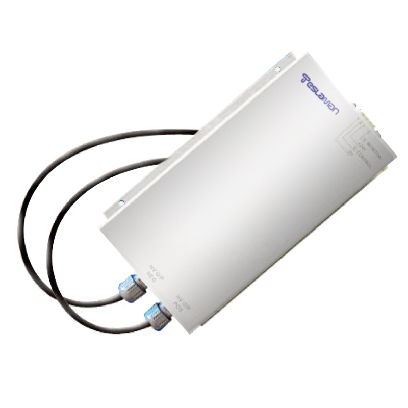
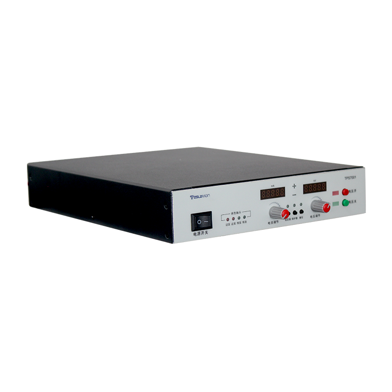
Plastic sorting facilities use electrostatic separation to divide mixed recyclables, and the high-voltage supply that charges the separating electrode governs the efficiency and purity of the process. Static charge control innovations on the supply side improve the recovery of valuable polymers from waste streams and reduce the amount of material sent to landfill.
Electrostatic separation works by charging particles and then deflecting the particles in an electric field. The supply voltage sets the field strength, and the stability of that voltage determines how consistently particles follow the intended trajectories. A fluctuating voltage spreads the particle paths and contaminates both output fractions, so the regulation quality is a direct economic factor.
Different polymers charge to different polarities and magnitudes. The supply supports a defined setpoint for each material recipe, and recipe changes are executed with a controlled ramp so that the field transitions smoothly without scattering particles. The recipe table stores the verified parameters for each polymer blend processed at the facility.
Particle size and moisture content modify the charging behavior. The supply compensates partially through voltage adjustment, but the practical answer is a process control loop that senses the separation quality and nudges the setpoint. Field trials show that automatic adjustment holds the output purity within specification across changing feedstock.
Feed rate variations change the load on the corona electrode. A surge of material draws more current and can pull the voltage down if the supply is not stiff. The regulation loop holds the voltage against the load change, and the current limit prevents an overload condition from shutting the process down mid-shift.
Arcing between the electrodes and the material flow is managed by the protection circuit. The arc detector clears the discharge and restores the field within a short recovery, and the arc count is logged. A rising arc rate indicates either wet feedstock or electrode contamination, and the log gives the operator a concrete trigger for intervention.
Environmental conditions inside the plant affect the separation. Humidity raises the conductivity of dust and reduces the effective charge, so the supply voltage is corrected against the measured humidity using a curve established during commissioning. The correction keeps the separation stable through seasonal weather changes.
Maintenance of the high-voltage section follows a defined schedule. The electrodes are cleaned, the cable terminations are inspected, and the supply output is verified against a calibrated divider. The verification record is kept with the process logs so that the correlation between supply drift and separation loss can be reviewed during an audit.
Energy efficiency of the supply affects the operating cost and the cooling load. The efficiency is measured at the representative operating points, and the improvement opportunities are evaluated against the implementation cost. The efficiency records are maintained for the lifetime comparison.
Training programs for the operating and maintenance staff are scheduled at defined intervals. The training covers the safe operation, the routine checks, and the fault diagnosis flow. The training effectiveness is verified with a written test and a practical exercise, and the results are filed with the personnel records.
Process qualification is performed whenever the equipment or the process recipe changes. The qualification plan defines the test articles, the acceptance criteria, and the data to be recorded. The qualification report is approved before the new condition enters production.
Failure analysis follows a defined path from the symptom to the root cause. The analysis uses the logged data, the physical evidence, and the repair records. The analysis conclusion is documented with the corrective action, and the corrective action is verified after implementation.
Quality records link the equipment performance to the product quality. The operating parameters and the product measurements are filed together, so that a product deviation can be traced to the equipment condition. The record retention period follows the regulatory and contractual requirements.
Vendor coordination covers the technical support, the spare supply, and the repair service. The service level agreement defines the response time and the repair turnaround. The vendor performance is reviewed periodically, and the review outcome influences the future procurement decisions.
Continuous improvement is driven by the analysis of the failure data and the operating experience. Each improvement proposal is assessed for the benefit, the cost, and the risk before implementation. The implemented improvements are tracked for the realized benefit.
Operator handover between shifts includes the equipment status, the pending issues, and the instructions for the current operation. The handover log is signed by both parties, and the entries are concise and factual. The handover discipline maintains the continuity of the operation.
Performance monitoring covers the key parameters that indicate the health of the supply. The monitoring points and the thresholds are defined during commissioning, and the measured values are recorded on a regular basis. The monitoring data support the early detection of the degradation trends.
Long-term stability of the supply is verified by the periodic re-measurement of the output characteristics. The measurements are compared with the baseline recorded at acceptance, and the drift trend is analyzed. A drift beyond the tolerance triggers a detailed investigation and a corrective action.
Troubleshooting flow guides the maintenance crew from the symptom to the probable cause. The flow is built from the documented fault cases and the component knowledge. The use of the flow shortens the diagnosis time and reduces the trial-and-error work.
System integration between the supply and the process controller is validated with the interface tests. The signal definitions, the timing, and the fault propagation are verified under the representative conditions. The integration records are kept with the system documentation.
Upgrade planning assesses the compatibility, the benefit, and the risk of each proposed change. The upgrade is implemented in stages with a verification at each stage. The upgrade records are updated in the configuration documentation.
Cost analysis of the equipment includes the purchase price, the installation, the energy, the maintenance, and the downtime. The cost data are collected over the service life and reviewed annually. The analysis outcome supports the replacement and the repair decisions.
Documentation of modifications records every change to the equipment, regardless of the size. The modification log includes the date, the reason, the implementer, and the verification result. The log is reviewed during the periodic audits to confirm that the documentation matches the hardware.