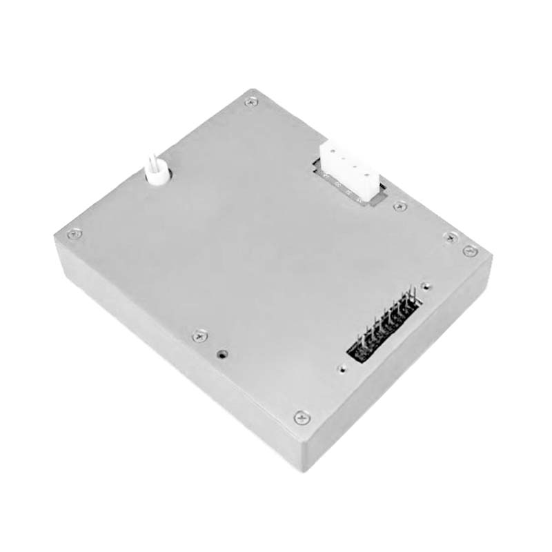
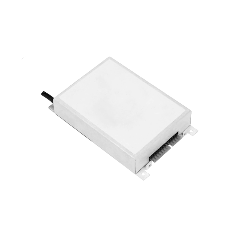
Cooling and Heat Dissipation Integration of Excimer Laser High-Voltage Power Supply in High-Power Laser Sources
Cooling and heat dissipation integration of an excimer laser supply deals with the concentrated losses of the charging stage. High pulse repetition raises the average power, the switching devices dissipate the switching loss, and the thermal path is sized for the worst operating point.
The charging converter carries the highest dissipation. The switch losses scale with frequency and current, the magnetic components add core and copper loss, and the heatsink is selected from the measured loss distribution rather than from nameplate ratings.
The cooling airflow enters at the front and exits at the rear. The duct directs the air across the heatsinks, the intake filter is sized for the flow, and the temperature sensors are placed at the hottest points identified by the thermal analysis.
Liquid cooling is applied where the power density exceeds the air-cooling limit. The coolant loop removes the heat to an external exchanger, the flow rate is monitored, and the interlock shuts the laser down when the coolant flow drops below the threshold.
Component placement supports the thermal design. The charging inductor and the switches sit in the main airflow, the control board is shielded from the heat, and the reference circuit stays in the stable temperature zone.
Thermal cycling from pulse operation drives solder fatigue. The temperature swing at each device is limited by the thermal mass, the cycle count is accumulated, and the maintenance plan uses the accumulated count for component replacement.
The heatsink-to-device interface controls the junction temperature. Thermal grease is applied evenly, the mounting torque is enforced, and the interface resistance is verified by the temperature rise measurement at full load.
Ambient temperature defines the cooling margin. The supply is rated for the site ambient, the derating curve is provided for higher temperatures, and the site is checked to confirm that the air inlet temperature stays within the design.
Temperature monitoring feeds the derating logic. The device temperatures are read continuously, a temperature approaching the limit reduces the allowed pulse rate, and the operator sees the derating status instead of a sudden trip.
Cooling failure is detected before damage occurs. The airflow sensor and the temperature sensors cross-check each other, an abnormal temperature rise triggers the protection sequence, and the laser stops in a defined state.
Field experience shows that filter maintenance decides long-term cooling performance. The intake filter is cleaned on a schedule matched to the site dust level, the airflow is verified after each cleaning, and the temperature trend reflects the improvement.
The thermal design is verified by a full-load endurance run. Temperatures are recorded over several hours, the steady-state values are compared with the analysis, and the verification data becomes the baseline for the site acceptance.
Voltage distribution across the capacitors of a multiplier stage needs balancing measures. Balancing resistors equalize the static distribution, capacitance matching controls the dynamic distribution, and voltage measurement confirms the result.
After relocation the insulation and grounding must be re-verified. Transport vibration can loosen connections, and the unit returns to service only after a new withstand test and a grounding check.
Separation of the control power from the power stage improves reliability. The control circuit has an independent feed, a power-stage fault does not disturb the control logic, and the post-fault state remains clearly defined.
Inrush at start-up is limited by a precharge circuit. A precharge resistor works with a bypass contactor, the bypass closes after precharge completion is confirmed, and contactor switching under load is avoided.
Data record resolution and sampling rate match the analysis needs. Slow trends and fast events are stored separately, and the event record keeps the waveform before the fault.
High-altitude application derates both insulation and cooling. Thinner air lowers the breakdown voltage and the cooling capability, design parameters are corrected by altitude, and test conditions simulate the site.
A power factor correction stage improves the grid-side behavior. Input current harmonics drop, reactive losses fall, the grid capacity requirement decreases, and harmonic testing verifies the result.
Product consistency is guarded by factory testing. Voltage accuracy, ripple, protection action and temperature rise are verified unit by unit, test data is archived, and batch variation is analyzed statistically.
Spare parts management follows the failure statistics. High-failure parts carry higher stock, long-lead parts are reserved in advance, and downtime shortens.
The remote maintenance channel needs security design. Permission levels, operation audit and data encryption are enforced, remote operations confirm the site condition first, and misuse risk stays bounded.
Residual charge discharge time at the output enters the safety procedure. Maintenance starts after the discharge completes, and the discharge indicator works with the mechanical interlock.
Online and offline insulation measurements complement each other. Online monitoring reflects the dynamic state, offline measurement gives absolute values, and the combination evaluates insulation health.
High-frequency noise is suppressed through the dual channels of shielding and filtering. Shielding blocks the radiation path, filtering attenuates the conducted path, and the two together meet the whole-unit specification.
Process parameters and supply parameters are archived together. Recipe numbers, voltage and current settings and batch results are linked, parameter changes leave traces, and quality traceability stays complete.
Insulation coordination starts with field distribution control. Electrode radii and shield placement determine the local field stress, and weak points show discharge precursors first. Field simulation verifies the stress margin at the design stage, and withstand testing confirms the result on the finished unit.
Filter network parameters balance ripple rejection against dynamic response. Larger output capacitance improves ripple but lengthens the voltage settling time, so the operating point is set from the actual load requirements rather than from a generic rule.
Thermal management decides power device lifetime. Losses concentrate in the switching devices and the magnetic components, and the heatsink thermal resistance plus the airflow path are sized for the worst-case duty. Temperature sensors are placed from the thermal analysis, and the data feeds the derating logic.
The reference and the divider network form the basis of voltage accuracy. The reference is selected for low drift, the divider resistors are matched, and the assembly is sealed against humidity. Calibration data is archived and periodic re-verification holds long-term precision.
Grounding practice controls the noise floor of control and measurement. Signal ground, power ground and chassis ground meet at a single point, ground loops are eliminated, and shield terminations follow a defined rule. Field commissioning verifies the grounding integrity before noise targets are assessed.