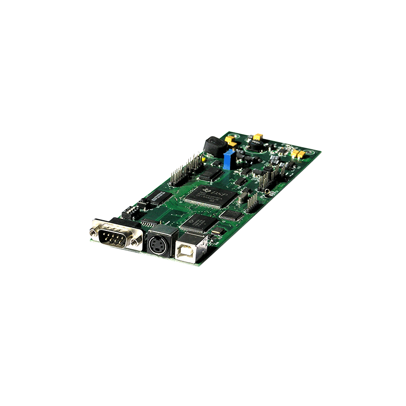
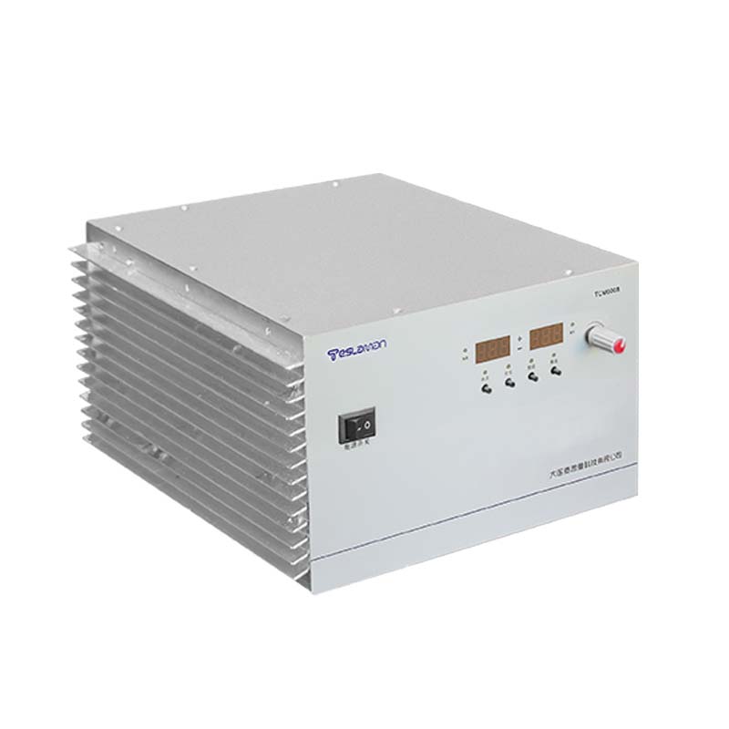
Adsorption Reliability of Electrostatic Chuck High-Voltage Power Supply in Semiconductor Transfer and Robot Handling
Adsorption reliability of an electrostatic chuck supply in semiconductor transfer and robot handling keeps the wafer fixed through the motion. The transfer step demands the fast and the repeatable chucking, the supply provides the defined voltage sequence, and the reliability is verified by the cycle testing.
The chucking voltage is set from the wafer size and the flatness. The voltage holds the wafer against the acceleration of the transfer, the adsorption force is verified, and the wafer deformation is limited.
The release step demands the residual charge control. The discharge path removes the charge, the counter-polarity pulse accelerates the neutralization, and the clean release prevents the particle generation.
The robot handling cycles the chuck continuously. The cycle time depends on the charge and the discharge speed, the supply supports the fast sequence, and the throughput is maintained.
The multi-zone control matches the warped wafer. The per-zone voltage is set from the wafer curvature, the force distribution is even, and the thin wafer breakage is reduced.
The supply protection covers the wafer contact fault. The overcurrent and the short condition are detected, the output is removed, and the recovery is manual after the inspection.
The vacuum environment affects the discharge behavior. The gas pressure changes the breakdown margin, the voltage is set within the safe window, and the operation in the vacuum is verified.
Reliability testing covers the repeated cycle. The chuck and the release are cycled, the force consistency is measured, and the accumulated cycle supports the maintenance plan.
The load characteristic affects the regulation. The capacitive load concerns the establishment time, the resistive load concerns the ripple, the pulsed load concerns the dynamic drop, and the field verification adjusts the setting.
The module temperature and the output capability are linked. The derating reduces the output at the high temperature, the derating curve follows the test result, and the rated operation returns after the condition recovers.
The field fault handling follows the symptom classification. The no-output case checks the supply and the protection, the output anomaly checks the feedback and the filter, and the insulation anomaly checks the environment and the aging.
The calibration is executed on the fixed schedule. The voltage and the current channels are calibrated point by point, the reference certificate is valid, and the deviation is corrected and re-verified.
The power-up self-test covers the critical paths. The sampling channel is verified, the protection logic is tested, the communication handshake is confirmed, and the abnormal item blocks the start.
The cable movement affects the measurement stability. The movement changes the distributed capacitance, the sampling chain receives the interference, and the fixed routing restores the repeatability.
The ambient temperature change causes the output drift. The compensation curve is generated from the measured data, the compensation covers the operating range, and the residual drift stays within the limit.
The high-voltage discharge test verifies the insulation margin. The test voltage rises by the standard step, the discharge level is monitored, and the breakdown point is located for the analysis.
The modular structure eases the maintenance. The faulty module is diagnosed independently, the spare stock follows the usage, and the replacement procedure is standardized.
The remote monitoring centralizes the management. The communication uses the unified protocol, the status data is uploaded in real time, and the alarm event is pushed with the record.
The inrush limiting protects the power-up. The limiting resistor and the relay cooperate, the inrush is measured, and the repeated start test verifies the repeatability.
The long-run attention is on the parameter drift. The output trend is recorded, the drift beyond the limit alarms, the aging is predicted, and the maintenance plan follows the data.
The field interference is located by the path analysis. The source is identified, the coupling path is analyzed, the shielding and the grounding are corrected, and the retest verifies the result.
The factory test covers the full performance. The voltage accuracy, the ripple and the response are verified item by item, the data is archived, and the nonconforming item is corrected.
The insulation aging is affected by the temperature and the humidity. The environment is controlled, the insulation state is checked periodically, and the partial discharge trend provides the warning.
The output power limit protects the high-voltage chain. The power beyond the limit triggers the derating or the shutdown, the recovery condition is confirmed, and the action is recorded.
The transport protection preserves the installation quality. The packaging absorbs the shock, the transport shock is monitored, and the incoming inspection checks the list and the appearance.
The feedback sampling delay affects the compensation. The delay source is identified, the compensation matches the bandwidth, and the step test verifies the adjustment.
The module parallel connection extends the output capability. The current sharing keeps the load balance, the faulty module is bypassed, and the thermal design follows the total power.
The output voltage accuracy of a high-voltage supply depends on the reference and the divider network. The reference is selected for the low temperature drift, the divider resistors are matched, and the periodic calibration keeps the accuracy within the specification.
The transformer insulation is designed for the rated voltage and the margin. The layer insulation thickness and the creepage distance follow the pollution degree, the encapsulation removes the voids, and the partial discharge test verifies the insulation quality.
The soft start circuit limits the inrush at the power-up. The starting resistor and the bypass relay work together, the bus voltage rises smoothly, and the inrush current stays below the rated limit.
The output filter is arranged for the ripple requirement. The equivalent series resistance of the capacitor controls the high-frequency attenuation, the resonance peak is damped, and the ripple is measured at the load terminal.
The thermal design follows the loss calculation. The conduction and the switching losses define the dissipation, the heat sink matches the thermal resistance, and the temperature rise test confirms the margin.
The protection logic is layered. The hardware comparator acts fast, the software logic confirms the event, and the recovery requires the manual reset after the cause is cleared.
Electromagnetic compatibility is handled at the structure level. The shield covers the sensitive section, the cable shield is terminated at one point, and the conducted and the radiated tests follow the standard procedure.