









Precision control of ion implantation high-voltage power supplies in flexible electronics and wide-bandgap semiconductors
An ion implanter supply delivers 80 kV at 5 mA to the acceleration column of an industrial ion implantation tool. The tool processes flexible-electronics substrates, 300 mm wide polymer webs, and wide-bandgap wafers, 150 mm silicon carbide discs. The beam current is held at 1 mA for the flexible substrates, and at 2 mA for the wafers. The dose is integrated over the implant time, and the supply ramps down when the target dose is reached. The dose uniformity across the wafer must stay within 1 percent, and the supply voltage ripple must stay below 0.1 percent to avoid beam energy spread.
The acceleration column is a series of 10 stainless steel electrodes, spaced 50 mm apart, inside a vacuum chamber. The supply connects to the top electrode, and the bottom electrode is grounded. The beam travels through the column, accelerated by the 80 kV potential difference. The column vacuum is 1e-4 Pa, maintained by a turbomolecular pump. The column insulation is ceramic, with a 300 mm creepage path between the high-voltage electrode and ground.
The beam current is measured by a Faraday cup at the end of the column, and the signal feeds back to the supply control board. The control board adjusts the acceleration voltage to hold the beam current at the setpoint. The feedback loop bandwidth is 100 Hz, fast enough to compensate for beam current fluctuations from the ion source. The loop once overshot when the ion source arc voltage dipped, and the beam current surged to 4 mA, double the setpoint. The overshoot was corrected by adding a lead compensator to the loop, and the overshoot dropped to 10 percent.
The flexible substrate implant runs at a lower beam energy, 30 kV, to avoid damaging the polymer web. The web moves at 10 mm per second through the implant chamber, and the beam scans across the web width of 300 mm. The dose is integrated over the web length, and the supply ramps down when the target dose of 1e15 ions per cm2 is reached. The web transport speed is synchronized with the dose integration, and a speed error of 1 percent causes a dose error of 1 percent.
The wide-bandgap wafer implant runs at 80 kV, with a beam current of 2 mA. The wafer sits on a water-cooled chuck, held at 20 degrees by chilled water. The wafer temperature rises to 60 degrees during the 5 minute implant, and the backside helium cooling keeps the temperature uniform across the wafer. The chuck voltage is separate from the acceleration voltage, supplied by a 5 kV chuck supply.
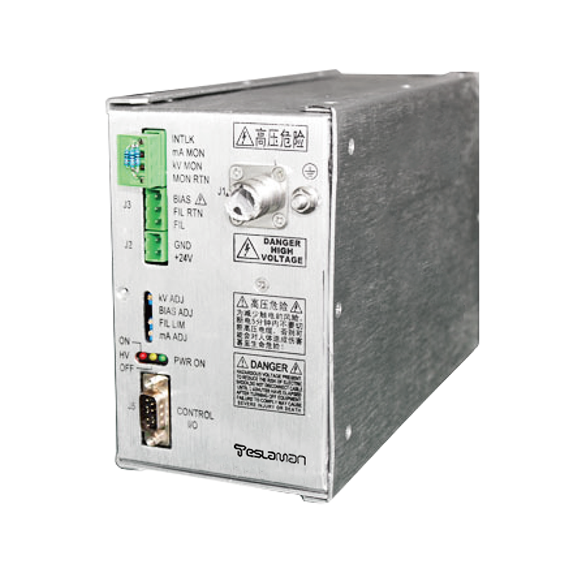
The high-voltage cable connects the supply to the acceleration column, through a 5 m shielded cable. The cable is an 80 kV silicone type, with the outer jacket grounded at both ends. The cable once developed a hairline crack in the jacket, and the leakage current rose from 1 μA to 15 μA. The leakage did not trip the 100 μA overcurrent threshold, but the extra 14 μA added noise to the beam current measurement. The cable was replaced at the next scheduled maintenance, and the leakage returned to 1 μA.
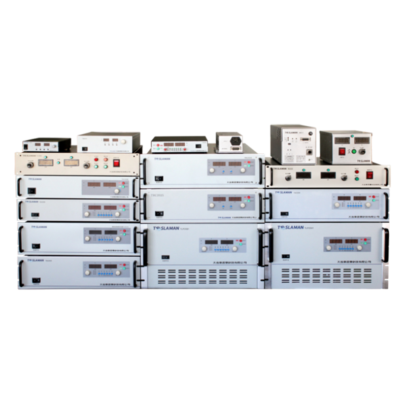
The supply cabinet is 800 mm wide, 1000 mm deep, 1800 mm tall, with IP54 protection. The cabinet contains the inverter, transformer, rectifier, divider, and control board. The cabinet cooling fans run on a thermal switch, starting at 35 degrees and stopping at 25 degrees. The fans once failed in summer, and the cabinet temperature reached 55 degrees. The electrolytic capacitors on the DC bus reached 65 degrees, above the 60 degree rating. The fan fault alarm now routes to the central monitoring room, and the fan is replaced within 10 minutes of alarm.
The control board uses a 16-bit ADC, sampling the output voltage at 1 kHz. The ADC reference is a buried-zener type, with a drift of 2 ppm per degree Celsius. The cabinet temperature is held at 25 plus or minus 2 degrees by the fan and heater, and the reference drift over a 24 hour operation stays below 10 ppm, equivalent to 0.08 V at 80 kV. The drift is within the 0.1 percent acceptance limit, and the reference is recalibrated annually against a 0.01 percent standard divider.
The safety interlock on the column access door was tested during commissioning. A technician opened the door while the supply was running, and the output dropped to zero within 20 ms. The residual charge on the output capacitor bled through a 10 MΩ resistor within 100 ms. The interlock response time was logged at 18 ms, within the 25 ms design limit. The column door carries a high voltage warning label, and entry requires a sign-in log. The beam interlock also trips the supply when the ion source arc extinguishes, and the arc sensor is checked quarterly.
The maintenance log lists routine tasks. Each shift, the operator records the output voltage, beam current, and cabinet temperature. Weekly, the technician inspects the cable jacket and the column feedthrough. Monthly, the insulation resistance is measured with a 2500 V megohmmeter, and the reading should exceed 1000 MΩ. Quarterly, the divider is calibrated against a 0.1 percent standard. Annually, the ADC reference is recalibrated. The log is signed at each step, and the record is filed in the plant archive.
The input side of the supply draws 400 V three phase at 15 A. A 50 kVA isolation transformer sits between the plant bus and the supply, to isolate the column ground from the plant ground. The isolation transformer has a 2500 V insulation rating between primary and secondary. The input cable is copper, 10 mm², rated for 35 A, routed through a cable tray. The input breaker is a 50 A molded case type, with electronic trip set to 1.05 times rated current long delay. The input power factor is 0.96, measured with a power analyzer during commissioning.
The high-voltage transformer inside the supply cabinet is oil insulated, with a 15 L oil volume. The oil temperature reaches 45 degrees after 8 hours of continuous operation at 80 kV and 5 mA, against an ambient of 25 degrees. The silica gel breather on the transformer tank changes color after 12 months, and the gel is replaced before the color reaches half saturation. The oil breakdown voltage is tested annually, and the last measurement showed 42 kV per 2.5 mm gap, well above the 25 kV replacement threshold. The transformer sound level is 50 dB at 1 m, measured with a sound level meter during commissioning.
The output divider is a series chain of 100 MΩ high-voltage glass glaze resistors, totaling 2 GΩ. The divider tap at 1:2000 feeds the control board ADC. The divider is calibrated quarterly against a 0.1 percent standard divider. The calibration drift over 12 months was 0.3 percent, equivalent to 240 V at 80 kV. The drift is within the 1 percent acceptance limit, but the divider is scheduled for resistor replacement at the 24 month mark.
The ion source is a Freeman type, with a tungsten filament heated to 2000 degrees. The filament life is 500 hours, and the filament is replaced preventively at 450 hours. The arc voltage is 80 V, and the arc current is 2 A. The arc voltage dip once caused the beam current surge, and the lead compensator was added to the beam current loop. The filament power supply is a separate 10 V, 100 A unit, isolated from the acceleration supply by a 100 kV transformer.
The vacuum system for the column uses a turbomolecular pump, rated at 100 L per second, backed by a rotary vane pump. The column base pressure is 1e-4 Pa, measured by a hot cathode ionization gauge. The gauge is calibrated annually, and the drift is checked quarterly. The gauge once drifted, reading higher than the actual pressure, and the column ran at 5e-3 Pa instead of the required 1e-3 Pa. The drift was caught during a quarterly check, and the gauge was recalibrated. The turbomolecular pump cooling water flow is monitored at 3 L per minute, and a low flow alarm routes to the central monitoring room.
The customer acceptance test was run over three days. Day one covered the wafer implant at 80 kV, measuring dose uniformity and beam current stability. Day two covered the flexible substrate implant at 30 kV, measuring web transport synchronization. Day three covered the beam current response to arc voltage dips, injecting controlled dips and measuring the overshoot. The test report was signed by the customer representative, and the supply entered the 12 month warranty period.
The plant environment around the supply cabinet is held at 23 plus or minus 3 degrees Celsius, with 45 to 65 percent relative humidity. Winter heating raises the room temperature to 26 degrees, and the cabinet fan runs continuously. Summer cooling failure once pushed the room temperature to 32 degrees, and the cabinet internal temperature reached 50 degrees. The ADC reference drifted 0.3% during that week, equivalent to a 240 V error at 80 kV. The drift was corrected after the cooling unit was repaired, and the supply was recalibrated. The plant floor is epoxy coated, cleaned daily with a vacuum cleaner, and the illumination is 300 lux with LED fixtures at 24 V.
The implant process data is recorded on the implanter workstation, with the run number, the dose, the beam energy, and the beam current. The data is stored for 5 years, and is available for customer audit. The quality department reviews the data weekly, and trends the dose uniformity. The data system generates a weekly report, showing the process yield and the defect rate. The report is distributed to the plant manager and the customer.
The implant bay safety audit is conducted annually, by an internal safety team. The audit covers the vacuum system, the high-voltage system, and the ion source gas supply. The audit report lists the findings, and the corrective actions are scheduled within 30 days. The last audit found one minor finding: a worn gasket on the column door. The finding was corrected within the scheduled time. The audit record is filed in the quality system.
The implant bay spare parts inventory includes: filaments, high-voltage cables, fuses, and Faraday cup collectors. The inventory is stocked at 20 percent of the annual consumption, and is reviewed monthly. The inventory is stored in a locked cabinet, and the key is held by the bay supervisor. The parts are logged out when used, and the log is reviewed by the quality department. The inventory was once depleted when a filament failed unexpectedly, and the stock was replenished within 2 days.
The implant bay operates two shifts per day, 6 days per week. The day shift runs the flexible substrate implants, and the evening shift runs the wide-bandgap wafer implants. The product changeover happens between shifts, and the wafer chuck is swapped. The shift handover includes a status report, listing the completed runs, the dose, and the beam energy. The handover log is reviewed by the bay supervisor, who allocates resources for the next shift.
The ion implantation process is qualified per SEMI Standard, with the dose uniformity and the beam energy tested. The test wafers are prepared alongside the production runs, and the wafers are tested after each batch. The dose uniformity is measured by a four-point probe, and the beam energy is measured by a time-of-flight system. The test results are recorded in the quality system, and the batch is released only when all tests pass. The process has maintained the qualification for 6 years, with no major findings in the last 3 audits.
The implanter vacuum system is maintained by the maintenance department, with weekly inspection and monthly preventive maintenance. The turbomolecular pump is backed by a rotary vane pump, and the pump oil is replaced annually. The vacuum gauge is calibrated quarterly, and the calibration record is filed in the quality system. The vacuum system has a 99 percent uptime target, and the downtime is logged in the maintenance record. The system once had a vacuum leak, and the leak was fixed within 6 hours, with no production loss.
The Faraday cup once read 8 percent low during a run of 50 silicon carbide discs, and the implanted dose came out 8 percent above the recipe target. The cup mouth carries a suppressor electrode held at minus 200 V to pull secondary electrons back into the cup cavity. The suppressor resistor chain drifted after 14 months of continuous use, and the suppressor voltage sagged to minus 120 V. Secondary electrons escaped the cup mouth, the electrometer undercounted the collected charge, and the dose integrator kept the beam on longer than the true dose required. The undercount surfaced when a four-point probe sheet resistance read 8 percent below the recipe value on the first lot. The suppressor chain was rebuilt with 0.1 percent metal film resistors, the suppressor voltage was rechecked at minus 200 V plus or minus 2 V, and the next 4 lots landed within 1.2 percent of target. The suppression voltage is now logged weekly on the maintenance checklist, and a drift beyond minus 180 V opens a recalibration ticket. Running with the suppressor bias off would read low by roughly the secondary yield, and on this tool that yield sits between 6 and 10 percent for 80 kV beams, so the suppressor bias cannot be switched off during production.
The supply has run for 20 months. The high-voltage cable has been replaced twice. The output capacitor shows a 4 percent capacitance loss, still within the 10 percent threshold. The unresolved issue is the beam current overshoot when the ion source arc dips. The lead compensator reduced the overshoot from 100 percent to 10 percent, but the customer asked for 5 percent. A faster loop controller is under evaluation, and the upgrade is scheduled for the next controller board revision.