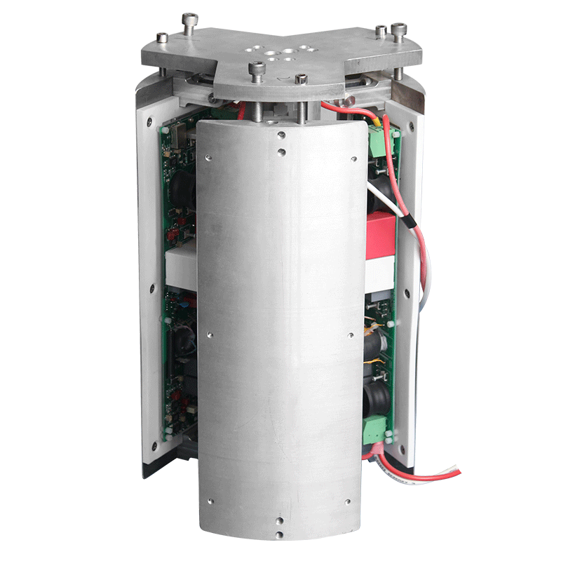
Optimization of ion implantation high-voltage power supplies in silicon carbide power devices and new 2D materials
Silicon carbide power device lines run aluminum implantation at energies between 350 and 600 keV, because the dopant must reach 0.4 to 0.8 micrometer depth through the epitaxial layer before activation anneal. The acceleration column supply holds the terminal at 550 kV setpoint, extracts the beam at 6 mA aluminum plus current, and feeds a 150 mm wafer scan that moves at 400 mm per second. Dose for the p-well step targets 5e15 per square centimeter, integrated from a Faraday cup reading taken every 10 milliseconds. The terminal supply floats in an SF6 tank at 0.4 MPa, and the column stacks eight ceramic insulator modules, each holding 70 kV. Ripple on the acceleration voltage stays under 80 V peak to peak, which translates into an energy spread of 0.015 percent on the implanted profile. Wider ripple would show up as tailing in the sheet resistance map, and process engineers reject lots with spread above 0.8 percent across the wafer. The tank sits on vibration isolators, and the SF6 pressure monitor logs a slow loss of 0.01 MPa per year, topped up at the annual service visit. The isolator pads, 50 mm thick elastomer blocks, show no settling after 4 years, and the pad hardness checks out at the quarterly visit.
Beam loading droop is the first fault noticed at production ramp. When the scan beam sweeps from the wafer edge into the Faraday, the effective load on the column shifts by 0.8 mA, and the terminal voltage dips 220 V for about 300 microseconds before the loop recovers. The droop shows up as a dose deficit on the first 2 mm strip at the scan turnaround. Compensation taps the scan waveform and pre-biases the setpoint 180 V high during the turnaround window, and the deficit falls from 4 percent to under 0.6. The pre-bias table was tuned on three product recipes before release, and the fourth recipe, a shallow n-type implant at 80 keV, needed a smaller pre-bias of 40 V because the lower energy makes the profile more sensitive. Over-compensation on that recipe once caused a 2 percent over-dose strip, caught at sheet resistance mapping before the lot moved to anneal. The turnaround window length, 50 milliseconds, matches the scan direction reversal, and the pre-bias drops off the moment the beam re-enters the wafer area. The Faraday cup current reading during the turnaround shows a 10 mA spike as the beam dumps into the cup, and the dose integrator pauses during the spike to avoid counting the extra current.
Column insulation aging sets the overhaul clock. After 800 operating hours, hydrocarbon residues from the source vacuum coat the inner surface of the ceramic modules, and flashover begins at 90 percent of rated voltage. The first sign is a faint crackling noise during ramp, heard through the tank wall, followed by a slow drift in terminal current of 15 microamps per hour. Planned column clean happens at 900 hours, at a cost of 14 hours of line downtime plus re-conditioning runs. The clean wipes each module with solvent and re-pressurizes the tank with fresh SF6, and post-clean flashover voltage recovers to 110 percent of rating. One chamber skipped the clean at 900 hours and took a full flashover at 550 kV, which cracked two ceramic modules and pushed the repair bill past the supply annual lease cost. The maintenance planner now blocks the calendar at 850 hours and refuses recipe runs that would push past the block. The cracked modules, replaced during the repair, left burn marks 30 mm long on the ceramic inner surface, and the inspection report filed with the vendor lists the residue composition as carbon and fluorine compounds.
Source arc supply behavior drives uptime more than the column does. The arc chamber sits at 120 V and 3 A for the aluminum feed, and the supply must recover within 50 milliseconds after an arc quench. Arc frequency on a fresh source runs 2 to 4 per hour; after 200 hours of source life, the count climbs to 25 per hour as the cathode filament thins. Each arc quench blanks the beam for 80 ms, and the dose integrator pauses during the blank so the wafer dose does not drop. Sources are swapped at 250 hours regardless of condition, though two chambers on the floor run past 300 hours during peak demand, accepting a higher arc count as the price of no source swap. The filament supply draws 22 A at 4 V, and the filament current drift over a 24-hour shift measures 0.3 A, which translates into a beam current drift of 4 percent. The dose loop compensates through the integrator, but the beam current display on the operator screen reads low enough to cause alarm clicks from the night shift. The source chamber water cooling runs at 1.5 liters per minute, and the inlet temperature holds 25 degrees. The water flow alarm trips at 1.0 liters per minute, and the trip has fired twice in three years, both times on clogged filters.
Two-dimensional material lines run a separate, much gentler implantation cell. Damage thresholds on monolayer flakes make conventional scan implantation impossible, so the line uses plasma doping at 1.5 keV acceleration and a beam current limited to 0.2 mA. Dose targets sit near 1e12 per square centimeter, two orders below the silicon carbide process, and the whole wafer stays below 80 degrees Celsius to avoid flake delamination. The low-energy supply is a compact 5 kV deck sharing the same control rack as the high-energy column, switched by a high-voltage relay that takes 200 ms to transfer. Ripple on the low-energy deck spec sits at 3 V peak to peak, because energy spread below 0.1 percent matters more for these thin layers than for the thick epitaxial profiles. Uniformity over the 100 mm substrate holds at 1.2 percent, looser than the 0.8 percent accepted on silicon carbide, and nobody on the floor sees reason to tighten the spec. The flake coverage density is low enough that averaging masks the variation anyway. The plasma chamber for the low-energy cell runs at 0.3 Pa process gas, and the extraction grid sits at minus 1.5 kV relative to the plasma. Grid erosion after 500 hours shows as a 0.2 mm widening of the aperture, and the grid replacement costs 1200 dollars plus 6 hours of pump time.
Charge neutralization on the 2D cell needs a dedicated supply channel. Insulating substrates charge up during implantation, and without electron flood the wafer surface potential drifts positive by 40 V, which slows the incoming ions and smears the dose profile. The flood gun sits at minus 60 V relative to ground, driven by a 0.5 mA supply that pulses on whenever the beam enable is active. Flood current tracks the beam current at a 1.1 ratio, and the loop keeps the substrate potential within plus or minus 2 V as measured by a Kelvin probe near the wafer edge. When the flood supply drifted to 0.8 mA on one chamber, the profile depth shifted 8 nanometers on the first lot, caught at secondary ion mass spectroscopy sampling before more lots ran. The flood gun filament, a 0.3 mm tungsten wire, lasts 400 hours and costs under 20 dollars, but the swap requires a vent of the load lock and 3 hours of pump down. Spare filaments sit on the shelf in packs of ten. The Kelvin probe needs recalibration every 3 months, because the probe tip dusts over with process material and the reading drifts 5 V high. The recalibration uses a known voltage reference on the chamber wall, and the procedure takes 20 minutes.
Mass analysis magnet stability sets the mass resolution margin. The bending magnet supply holds 950 A at 18 V for the aluminum mass line, and the current ripple spec sits at 100 ppm peak to peak. A 0.1 percent drift in magnet current shifts the mass slit edge enough to let magnesium plus contamination through, which shows up as a 0.5 percent rise in sheet resistance on the out-of-spec lots. The magnet coil water cooling runs at 22 degrees inlet, and the coil temperature climbs 6 degrees under load. The supply cabinet fan was upsized after the second summer, because the original fan curve let the cabinet hit 45 degrees on hot days and the magnet current reference drifted 200 ppm. Reference drift now stays within the 100 ppm band, and the magnet supply gets a weekly current check against a shunt standard traceable to the in-house calibration bench. The mass slit, a 0.5 mm tungsten aperture, heats under beam interception and shows thermal expansion of 2 micrometers at full beam. The slit cooling loop runs at 1 liter per minute, and the slit temperature holds 35 degrees. Slit alignment check happens at the annual column clean, and the alignment tolerance is plus or minus 0.1 mm.
Wafer scan generator linearity affects uniformity at the turnaround. The scan coils move the beam across the wafer at 400 mm per second, and the scan waveform traces a triangular path. Linearity error in the scan amplifier shows up as a dose strip near the center of the wafer, where the beam spends more time than the recipe assumes. The scan amplifier board gets a monthly linearity check, and the error band sits at 0.5 percent. When one amplifier drifted to 2 percent in 2024, the center strip showed 3 percent higher dose, and the sheet resistance map showed a 1.5 percent dip in the center ring. The amplifier board swap took 4 hours, and the spare board costs 3400 dollars. The scan coil current, 8 A peak, runs through a water-cooled coil, and the coil temperature holds 40 degrees. The scan waveform reference, generated by the control rack DAC at 16 bits, updates the coil current every 100 microseconds.
Line shift operations show the real trade. Recipe changeover between silicon carbide implants and 2D doping takes 45 minutes of pump and pump again, plus a 10-point dose calibration run on a witness wafer. The calibration run consumes 2 wafers per change, and the fab runs 6 to 8 recipe changes per day on a mixed product floor. Fewer changeovers would smooth throughput, but the product mix forces the schedule. Dose nonuniformity across a mixed day runs 0.9 percent average, against 0.6 percent on dedicated days, and the process group accepts the penalty. The terminal supply settles within 5 minutes of a recipe switch, which is not the bottleneck; the bottleneck stays at the vacuum and the source warm-up. On the busiest shifts, the operators pre-stage the next recipe setpoint while the current wafer finishes, so the supply ramps in parallel with the pump. The routine works, and the day shift has stopped logging the changeover delay as a fault. The spare parts stock, reviewed monthly, keeps two spare source chambers, one spare filament supply, and one spare scan amplifier on the shelf. The shelf check also verifies the SF6 cylinder stock, and the cylinder exchange happens at the annual tank service.
Faraday cup conditioning sets the dose measurement drift. The cup, a cooled tungsten aperture in the beam path, intercepts no beam during normal operation, but secondary electrons from the wafer edge drift into the cup and show up as a 2 microamp background on the integrator. The background drifts 0.5 microamp per week as cup walls coat with process material. Conditioning, a 15-minute low-power plasma clean inside the cup chamber, cuts the background back to 1.5 microamps, and the routine runs every 2 weeks. The cup signal cable, a shielded triax running from the chamber to the control rack, gets a quarterly insulation check, and the cable resistance reads 10 gigaohm on a clean unit. A damaged triax shield on one chamber let noise couple into the cup signal, and the dose reading wandered 1 percent for 3 shifts before the fault was traced. The cable replacement took 8 hours, and the spare triax costs 380 dollars.
High-voltage deck maintenance at the annual shutdown covers the whole column. The deck modules come out one by one, wipe with solvent, inspect the ceramic surfaces for discoloration, and re-seat the high-voltage connectors. The connector torque, 2.5 Nm, gets checked on every module. The deck power supply, a 48 V DC unit on the rack bottom, gets a ripple check, and the ripple spec sits at 50 mV. The spare deck module on the shelf costs 4200 dollars, and the module exchange takes 2 hours plus a 4-hour conditioning run. The conditioning run, a low-current ramp to 80 percent of setpoint, takes 4 hours, and the ramp table was re-parameterized after a 2023 event where a too-fast ramp cracked a ceramic module. The re-parameterized ramp rises at 5 kV per minute, with a 10-minute hold at 50 percent setpoint before the final step to 80 percent.