Energy input of 225 kV high-voltage power supplies in electron beam surface treatment and alloying
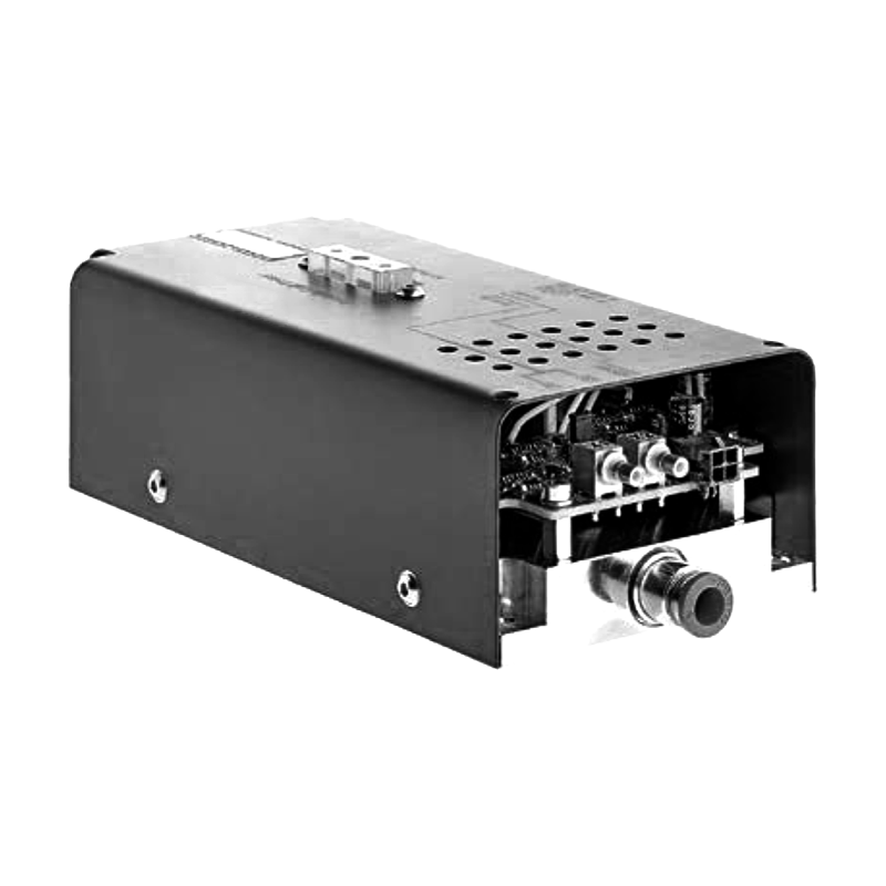
The electron beam treatment line in the shop hall runs a 225 kV gun supply feeding a triode gun mounted on top of a 4 cubic meter vacuum chamber. Rated beam power sits at 15 kW, continuous through the gun aperture, and the emission loop holds 70 mA at full setting. The work table travels on two axes at 0.2 to 8 mm per second, and the chamber holds 6e-2 Pa during treatment, backed by a roots pump plus oil diffusion pump stack. Surface alloying jobs run on medium carbon steel plates up to 20 mm thick, and the plates carry a preplaced powder layer before pump-down. Energy input for a standard pass lands at 2.4 kJ per square centimeter, split across 3 overlapping sweep bands. The supply cabinet sits 9 meters from the chamber on a dedicated 380 V three-phase feed, and the HV connection uses an oil-filled ceramic feedthrough rather than a flexible cable, because flexible cable capacitance above 100 kV absorbs the sweep signal and broadens the spot edge. Spot diameter at the work measures 6 mm at 120 mm working distance, and the sweep coils fan the spot into a 40 mm wide strip.
Energy input density sets the melting depth, and the recipe table lists three bands. A shallow band at 1.6 kJ per square centimeter melts 0.35 mm into the base and leaves most of the preplaced powder as sintered porous material, which washes out in the post-grit blast. A medium band at 2.4 kJ melts 0.6 mm and dilutes the powder layer into the steel at about 25 percent mixing ratio, the target for wear-resistant shaft sleeves. A deep band at 3.8 kJ melts 0.95 mm, dilutes past 40 percent, and cracks appear at the heat-affected zone on plates thicker than 12 mm. The sweep speed during the medium band holds at 3.2 mm per second, and one pass covers 40 mm width with 8 mm overlap between strips. Too slow a travel lets the melt pool boil and spit droplets onto the chamber wall, and the shop staff once saw 0.2 mm droplets collect on the viewport glass after a 4-hour run. The energy number comes from beam voltage times emission current times dwell over the strip area, and the line crew checks the arithmetic against a calibrated Faraday cup pull once per week.
Preplacement of the alloy powder drives more variation than the supply settings. The powder mix, a chromium-boron-iron blend sized 45 to 100 micrometers, gets spread with a polymer binder dissolved in acetone, and the layer sits 1.5 mm thick after drying. Uneven layer thickness by 0.3 mm changes the absorbed energy enough to swing the melted zone width by 12 percent across a single plate. The binder burns off during pump-down and the first 30 seconds of beam warm-up, and any binder residue left at 100 Pa pressure pushes the chamber pressure up to 2 Pa and trips the pressure interlock on the gun supply. A longer bake step at 150 degrees on the table heater solved the trip rate, but the bake adds 45 minutes per batch and cuts daily throughput from 22 plates to 17 plates. Powder batch moisture, measured with a loss-on-drying test, stays below 0.3 percent per lot, and a single wet lot in spring produced a foamed, porous alloyed layer that failed the hardness traverse at 3 locations.
The sweep generator supplies two deflection coils with a triangular current waveform at 200 Hz, and the coil current ramps 2.5 A peak to peak. At the strip edges, the triangle overshoots the table motion and leaves 2 mm of untreated border on each side, and the recipe compensates by overlapping strips by 8 mm instead of the nominal 4. The sweep amplifier inside the supply cabinet shares the 225 kV tank, and the coil wires cross the tank wall through matched feedthrough capacitors that block DC while passing the 200 Hz ramp. A ringing problem on the coil current, seen as a 15 percent ripple on the strip hardness map, traced to the feedthrough capacitors drifting 20 percent in value after 18 months of heat exposure near the tank wall. The capacitors moved to an external rack cooled at 24 degrees, and the ripple on the hardness map dropped back under 4 percent. The swap took one shift, and the line has not repeated the move.
Grid bias on the triode gun switches the beam on and off between strips. The bias supply holds minus 800 V at cut-off and minus 200 V at full emission, and the loop turns the beam off in 12 microseconds when the table reaches a strip end. Blankoff during repositioning prevents stray beam heating of the table rails, and the rails show no discoloration after 18 months of operation. The bias reference derives from the same voltage divider that samples the 225 kV output, so a divider drift moves both the beam energy and the cut-off point. Divider taps get a yearly clean with dry nitrogen, and resistance check of the 12-stage chain reads within 0.5 percent of nominal. One dirty tap in 2024 shifted the effective beam energy down 1.2 percent, which showed as a faint under-melt band running along every plate edge for 3 days before the maintenance crew caught the trend on the hardness logs.
Vacuum arcs during treatment stop a job faster than any other fault. When a melt pool spits a droplet into the beam path, the droplet vaporizes and a low-pressure arc fires between cathode and anode, pulling emission up past 120 mA in under 10 microseconds. The arc detector on the supply trips the HV enable within 8 microseconds and clamps the bias to minus 1500 V, and the table pauses in place. Recovery sequence waits 40 ms for the arc plasma to clear, then ramps beam back at half power for 200 ms before returning to full. On dusty powder layers, arc frequency runs 3 to 6 events per hour, and each event leaves a 2 mm re-melt spot on the surface that gets ground out in post-processing. Raising the trip threshold to 150 mA was tried on one shift and let a real arc burn a pinhole in the anode aperture, costing a 14-hour anode replacement. The threshold went back to 120 mA.
Heat balance across the plate decides distortion. The back side of each plate sits on a water-cooled copper platen held at 28 degrees, and platen contact under a 20 mm plate removes about 60 percent of the beam heat. The remaining heat raises the plate center to 480 degrees during a full strip pass, and infrared imaging from the chamber viewport tracks the rise at 12 Hz sampling. Plates thinner than 6 mm bow 1.5 to 2 mm after treatment, and the straightening press at the end of the line takes two passes to bring the bow under 0.3 mm. The press step was added after the first batch of 3 mm wear shims came back out of tolerance and went to scrap at 42 pieces. Preheating the platen to 80 degrees before treatment halves the bow, and the recipe now starts every job with a 10-minute platen preheat on parts under 8 mm.
Hardness traverse after treatment checks the energy input budget. A standard sleeve job shows 61 to 63 HRC in the alloyed zone, dropping to 42 HRC in the heat-affected zone and 20 HRC in the unaffected core. Zone depth measured on the metallographic mount reads 0.58 mm against a target of 0.60 mm, spread 0.04 mm across a 22-piece batch. When the energy input drifted down 8 percent over a month, the zone depth fell to 0.48 mm and hardness dropped to 57 HRC, which the incoming inspection of the wear parts caught on the third batch before shipment. The drift traced to emission loop calibration: the internal shunt had warmed 11 degrees above the calibration temperature, and shunt resistance changed 0.4 percent per 10 degrees on that grade of manganin. The shunt moved off the tank wall into the air-cooled section, and drift since then stays under 1 percent over a shift.
Cathode filament life sets the longest scheduled downtime. The tungsten hairpin filament runs at 22 A heater current, and emission capability decays from 80 mA to the 70 mA work point over 120 operating hours. Replacement takes 3 hours, including vent, gun column open, filament swap, and pump-down back to 6e-2 Pa. The line keeps two filament spares on the shelf, and each spare costs 340 dollars. Filament evaporation deposits a thin tungsten coat on the grid aperture, and the grid draws 0.5 mA of leakage after 100 hours, enough to bias the cut-off point slightly off. The grid gets a physical wipe with tungsten-free abrasive at every filament change, and the wipe takes 20 minutes. A failed wipe on one gun left grid leakage at 2 mA, and the beam shut off late during a strip, leaving a 15 mm untreated gap on 9 plates.
Mains interaction shows up on long starts. The shop hall transformer feeds several 15 kW welders on the same bus, and a weld cycle starting while the beam ramps pulls the 380 V bus down to 365 V for 80 ms. The gun supply holds regulation through the dip, but the filament heater supply, an open-loop 22 A unit, dips with the bus and lets cathode temperature sag, which cuts emission 6 percent during the dip. The sag appears on the hardness map as a faint band every time the nearby weld station fires. A dedicated 15 kVA regulator between the shop bus and the gun cabinet smoothed the dip to 2 V, and the faint bands disappeared. The regulator occupies 0.4 square meters of floor space and adds 3 percent to the hall power bill, and the line accepted the cost after three batches went to the grit blast rework rack.
Chamber wall coating grows into a maintenance item. Sputtered iron and chromium from the melt pool builds a mirror-like layer on the stainless chamber wall after about 80 hours of treatment, and the layer starts flaking when thickness passes 0.2 mm. Flakes falling on a hot plate surface cause arc events and pinholes, so the crew wipes the wall with a nylon brush at every 40-hour interval. The wipe takes 2 hours per chamber open, and the vacuum pump stack absorbs the extra air exposure through a 30-minute pump-down extension. The viewport glass gets a fresh cover slide at the same interval, and the stock of cover slides runs 120 pieces per year. An aluminum foil lining on the upper wall was tried for one quarter to simplify cleanup, but the foil outgassed at treatment temperature and pushed pressure readings up 0.8 Pa, and the lining came out.
Austenitic stainless plates ran as a trial last spring and exposed a gap in the parameter table. On steel, the medium energy band works without side preheat, but on the 304 grade the same 2.4 kJ band produced incomplete powder fusion at the strip edges, where the spot intensity falls off. Edge fusion improved only after the sweep band widened from 40 mm to 46 mm and the edge overlap rose to 12 mm, which cut the effective width per pass and pushed cycle time up 18 percent. The trial produced 50 shaft sleeves for a pump rebuild job, and all passed hardness at 59 to 61 HRC. The parameter table for stainless still carries a caution note on the printout, and nobody has run a second stainless lot long enough to clear the note.
Power metering on the cabinet reads 21 kW drawn from the wall at 15 kW beam output, and the difference covers tank heating, pump power, sweep amps, and losses in the HV multiplier stack. Efficiency sits at 71 percent, and the tank cooling loop dissipates 4.5 kW through an oil-to-water exchanger held at 26 degrees inlet. The oil temperature alarm sits at 55 degrees, and the log shows one alarm in 14 months, traced to a clogged exchanger filter after a summer month when the hall cooling failed for 2 days. Filter replacement takes 40 minutes, and the filter cartridges now go on a 6-month schedule instead of the yearly schedule written in the manual. Energy cost per treated plate averages 1.8 kWh, and the accountants track that number against the wear-part replacement cycle at the customer plant.
Table drive accuracy hid a fault that appeared late in production. The two-axis table runs on ball screws driven by servo motors, and position feedback comes from rotary encoders on the motor shafts, not direct scales on the table. A worn screw nut on the cross axis accumulated 0.4 mm of backlash over 18 months, and backlash showed as strip-to-strip spacing error that the hardness traverse spotted as a wavy border along alloyed edges. The nut replacement took 6 hours and required realignment of the zero datum, and the datum check uses a reference block with a scribed line aligned under the viewport. Position repeatability after replacement reads 0.05 mm across the 500 mm travel, and the line now logs table position error from the servo following error readout once per shift. Following error over 0.03 mm triggers a check, and the alarm caught a second nut wearing on the longitudinal axis 6 months later, before the wavy border showed up on product. Limit switches at the table ends get a function test during the weekly maintenance visit, and a failed switch on the positive cross axis in 2023 let the table run into the hard stop, cracking the nut housing and stopping production for 2 days.