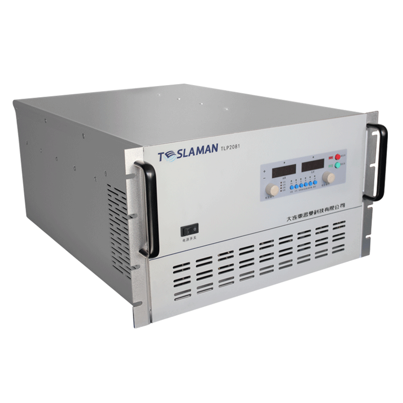
Noise management of low-ripple high-voltage power supplies in high-voltage precision resistors and voltage dividers
The high-voltage test room on the second floor houses two low-ripple supplies that feed divider ratio benches. One unit holds 100 kV at 2 mA maximum, the other 60 kV at 5 mA, and both drive the high arms of precision dividers under calibration. The room stays at 23 degrees plus or minus 0.5 through a ceiling-mounted cooling array, and floor covering is conductive rubber laid over a 4 mm copper grid. A divider under test hangs on a 1.8 m insulating frame, top terminal near the ceiling and bottom tap within reach of a six-and-a-half digit multimeter. Ratio checks run at 10, 30, 60, and 100 kV, and each point holds for 5 minutes before the reading logs. The supplies sit in a corner rack separated from the divider frame by 3 meters, and the HV run between rack and frame uses rigid enameled rod rather than coaxial cable, since cable capacitance would load the output and distort the transient on voltage step.
Ripple on the supply output sets the floor of the whole measurement chain. At 100 kV setpoint, residual ripple reads 48 mV peak to peak on a 100 MHz oscilloscope across a terminated divider tap, which works out to 0.48 ppm of the full-scale voltage. The divider steps that down by the 1000-to-1 ratio, so the tap carries 100 V plus 0.048 mV of ripple. The multimeter integrating noise floor sits near 0.03 mV on the DC range, which leaves almost no margin, and the bench log records ratio values to 6 decimal places on the strength of averaging 100 samples over 10 seconds. Dropping the ripple spec from 50 mV to 20 mV would require an extra LC stage in the output filter, and the unit price would climb 22 percent. The shop chose the 50 mV unit because the divider self-heating drift, around 0.2 ppm per 5 minutes, already swamps the ripple contribution.
Switching noise escapes the shielded tank through paths the schematic does not show. The primary side inverter runs at 24 kHz, and the 24 kHz component reappears on the divider tap at 12 microvolts even though the supply ripple spec covers only the 100 Hz envelope. A second oscilloscope probe on the tap tap reads the component through the 1 m ground lead, and the lead length turned out to matter: cutting the lead from 1 m to 0.1 m dropped the picked-up 24 kHz by a factor of 4. The bench now uses a spring-loaded probe tip with the shell bonded straight to the divider guard ring, and the 24 kHz residual holds under 3 microvolts. A metal plate under the divider frame, grounded at one star point, further cut the electric-field pickup, and the plate cost 900 dollars in copper and brackets.
Thermal voltage in the divider arms competes with supply noise on cold mornings. Each divider arm series chain contains 200 foil resistors, and every resistor end cap joins a copper bus by a small braid, generating a Seebeck voltage at the joint. Room temperature swings of 1 degree between 8 a.m. and 10 a.m. shift the tap reading by 0.06 mV, which on a 100 V tap equals 0.6 ppm. The bench routine now waits 40 minutes after room lights reach full output before the first ratio reading, and the logbook shows morning readings stabilizing within 0.15 ppm after that wait. The supplies contribute a smaller thermal term, since the multiplier diodes warm the oil in the tank and drift the divider reference taps by 0.1 ppm per hour in the first 2 hours after switch-on. A clock rule forbids ratio logging inside the first hour of supply warm-up.
Corona at the top electrode adds a quiet current that the ripple measurement hides. At 95 kV, a sharp corner on the divider top fitting started corona with a faint hissing heard in the room after hours, and a corona current of 1.8 microamps showed on the supply display as a slow upward creep of the current reading. The creep integrates over 5 minutes as a 0.9 ppm ratio shift, because the divider lower arm sees the leakage as added load. Replacing the sharp fitting with a 60 mm diameter toroidal grading sphere cut the corona onset from 95 kV to above 110 kV, and the creep disappeared. The sphere adds 450 dollars to each divider build and forces the frame to grow 12 cm taller, which the room ceiling just clears with 5 cm of margin.
Self-heating inside the divider moves the ratio more than supply regulation error. At 100 kV, the divider chain dissipates 1.2 W, spread over a 1.5 m column, and the column warms 1.2 degrees in the first 5 minutes. Foil resistance shifts 0.1 ppm per degree, so the ratio drifts 0.12 ppm per measurement point on a cold start. The bench procedure logs the first point as warm-up data and excludes the point from the calibration certificate, and the customer receiving inspectors know the exclusion from the procedure sheet. A heavier divider design with double the resistor count halves the self-heating but doubles the column cost, and the shop sells the heavy version only to customers who specify ratio uncertainty below 1 ppm. Such customers make up about 15 percent of orders.
Ground loops between bench instruments inject mains-frequency hum. The multimeter power supply, the supply control PC, and the divider tap scanner each tie to a different wall outlet, and the 50 Hz loop reads 2.5 mV on the tap when all three run. A star grounding bar mounted under the bench, with each instrument bonded by a separate 6 mm wire, cut the hum to 0.2 mV. One outlet circuit shared by the supply cabinet and the bench computer kept the loop alive for 2 weeks, and the service electrician moved the computer to a separate circuit after the hum appeared on a customer certificate and had to be reissued. The reissued certificate cost the shop 6 hours of bench time plus a courier fee, and the wiring notes now forbid mixing supply cabinet circuits with instrument circuits anywhere in the room.
A fan bearing failure on one supply in 2023 taught a noise lesson that the ripple meter missed. Output ripple looked normal on the oscilloscope, at 52 mV, but ratio readings spread by 3 ppm across three repeat runs where the procedure expected 0.5 ppm. The spread traced to output filter capacitors: ESR had climbed from 0.8 ohm to 4.6 ohm as the electrolytics aged, which lifted the 100 Hz envelope component from 48 mV to 190 mV only under the divider load of 1 microamp. The bench ripple meter, reading an open-circuit probe, never saw the loaded ripple. The repair shop replaced all eight filter capacitors, and a loaded ripple check, at the working divider current, became part of the quarterly preventive visit. Since then, two more units showed rising ESR before any ratio spread appeared.
Load switching on the 60 kV bench exercises the supply transient response. Divider swapping between jobs disconnects the high arm for 30 seconds while the supply stays energized, and reconnecting onto an open output lets the supply overshoot 4 kV before the loop settles in 120 ms. The overshoot used to punch through two divider input resistors per quarter until the procedure added a hold resistor of 100 megaohms across the divider input, which drains the stray charge and limits the reconnect transient to 400 V. The hold resistor costs 80 dollars and gets replaced annually, and the quarterly resistor failure rate fell to zero. An alternative, ramping the supply down on every divider swap, would add 4 minutes per swap and slow the bench throughput by 12 percent, so the resistor option stayed.
Burn-in racks run off the same 100 kV supply after the daytime calibration work ends. Each rack holds 40 divider modules, each at 70 kV for a 24-hour burn, and the combined load draws 1.6 mA, close to the 2 mA rating. The supply then runs 14 hours unattended overnight, and the alarm log pages the on-call technician if output voltage deviates more than 0.2 percent. One autumn night, a cooling fan tripped on the rack mains contactor and the supply rode through at full voltage with the divider chain overheating, melting two modules before morning. The contactor now has a feedback auxiliary contact wired into the supply interlock, and the supply refuses HV enable unless the contactor confirms closed. The modification took one afternoon and cost 120 dollars in contact parts.
Divider manufacturing tolerance sets what the supply must achieve. A production divider leaves the line with ratio tolerance 0.05 percent and tempco 1 ppm per degree, and the calibration bench verifies both numbers. The supply must hold voltage stable enough not to contribute error above one tenth of the divider tolerance, which at 0.05 percent means the supply regulation needs 50 ppm or better. Installed units meet 30 ppm line and load regulation, measured at the factory, and drift 15 ppm over 8 hours. A customer once demanded 5 ppm supply drift, which required a separate reference divider in the tank and doubled the unit price, and the shop built two such units before losing the next bid on price.
A 200 kV X-ray bench customer returned a divider last winter with complaints of ratio instability above 150 kV. The bench recreated the symptom: tap readings wandered 4 ppm over 10 minutes whenever the divider passed 150 kV, while the supply ripple read 45 mV. Internal grading rings in the divider turned out misassembled, leaving a 2 mm gap between two rings that started a silent corona at 155 kV. The fix sat inside the customer divider, not inside the supply, and the supply data log over the return trip already showed the current creep signature of 1.6 microamps that nobody had flagged. The log review added a current-creep alarm at 1 microamp per 5 minutes, and the alarm has fired twice since, both times on dividers with internal faults rather than supply faults.
The divider top contact assembly caused a slow complaint that nobody connected to the supply at first. Each divider clamps to the supply output stud through a beryllium copper finger cluster, and contact resistance across the cluster should read under 10 milliohms. After a year of room air, the fingers tarnish, and resistance climbs to 60 milliohms on units that never returned for service. At 1 microamp divider current, the extra resistance drops 60 microvolts on the tap, and the ratio reads 0.6 ppm low, small enough to pass most checks but enough to fail a tight customer who compares two dividers against each other. The shop added a finger cleaning step to the quarterly visit: a quick spray of contact cleaner, then a 20 Nm torque on the stud nut, and resistance back under 15 milliohms. A transformer test lab on a dividers-on-site service contract saw ratio mismatch complaints drop to zero after the cleaning step went in. The finger clusters on the bench dividers last 5 years before the fingers lose spring tension, and cluster replacement costs 210 dollars per divider and takes 1 hour. Tarnish rate tracks the room air: in winter, when heating dries the air to 20 percent humidity, tarnish slows and quarterly checks read clean; in summer, a 70 percent humidity room shows tarnish within 6 weeks.
The bench room faces east, and morning sunlight crosses the divider frame through a strip of window nobody remembered. Between 9 and 10 a.m. the sun warms the frame top rail by 3 degrees, and the rail warms the resistors near the top taps, shifting the ratio 1 ppm low during the window. The morning drift fell inside the allowable band only after the procedure moved ratio logging to the afternoon block, and a heat-reflecting roller blind went up on the window as a second fix. The blind cost 180 dollars and cut the frame temperature swing from 3 degrees to 0.8 degrees. The afternoon logging shift costs the bench 3 productive hours per day, and the estimator flagged the trade-off when ordering the blind. A second bench on the room inner wall, installed 2 years later, avoided the window problem entirely, and the original bench now handles only 70 kV jobs while the tighter ratio work moved across the room. The inner-wall bench reads ratio spread of 0.3 ppm across a 5-minute point, against 0.5 ppm on the window bench, and the customer certificates quote the tighter number. The divider warming time after a room setback follows the same temperature logic: the bench procedure forbids logging when the room heater cycles, and the heater cycle window, printed on the procedure sheet, runs from 6 a.m. to 8 a.m. on cold winter days. Skipping the heater window once on a rushed job produced a certificate that the customer auditor flagged, and the certificate had to be reissued at the next calibration visit.