Research on Key Technologies of High Voltage Power Supply for Gain Control in Microchannel Plate Detectors
1. Gain Generation Mechanism and High Voltage Coupling
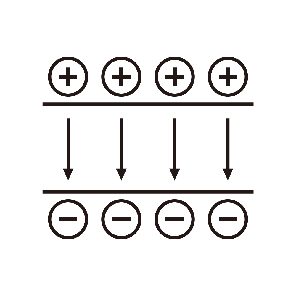
The gain characteristics of microchannel plates (MCPs) depend on precise high voltage regulation of secondary electron emission. When 800-1200V is applied across the channels, single-electron incidents trigger avalanche amplification of 10^3-10^4. Experiments show an exponential relationship between gain (G) and voltage (V) (G∝e^(kV)), where ±1% voltage fluctuation causes >15% gain deviation. Gradient electric field design (200-300V/mm at entry, 500-800V/mm at exit) optimizes electron trajectories, reducing wall collision losses and improving gain uniformity to ±5%.
Channel geometry significantly affects gain sensitivity. For 5μm-diameter channels, 1200-1500V with <0.01% ripple is required to avoid micro-discharge-induced gain oscillations. In multi-stage MCPs, interstage voltage differences must stabilize at 100-200V with leakage current <1nA to prevent nonlinear distortion.
2. Critical Design Elements of High Voltage Systems
1. Ultra-Low Ripple Output
Full-bridge LLC resonant topology with multi-stage filtering reduces ripple to <0.005%. Pulse-mode operation (10kHz-1MHz) with adaptive duty cycle adjustment enables dynamic gain ranges (10^2-10^6), supporting photon counting and intensity imaging.
2. Nanosecond Dynamic Response
GaN-based switches (>10MHz) reduce voltage adjustment latency to 50ns, mitigating gain saturation from transient light variations. Closed-loop feedback (±0.1% current monitoring) compensates for voltage gradient decay caused by channel aging.
3. Distributed Voltage Division
Thick-film resistor networks (±0.05% accuracy) limit interstage voltage drift to ±0.2V. Vacuum potting achieves 5ppm/℃ temperature coefficients, ensuring gain stability across -40℃~85℃.
3. System-Level Gain Optimization
1. Temperature-Voltage Compensation
A gain-temperature coefficient model (-0.3%/℃) combined with embedded thermocouples (0.1℃ resolution) limits gain fluctuations to ±2% in -20℃~60℃ environments.
2. Electron Injection Energy Control
A 50-100V pre-focusing electrode optimizes initial electron energy, increasing secondary emission coefficients from 2.5 to 3.8 and boosting gain by 52%.
3. EMI Shielding
A five-layer shielding structure (Cu-permalloy-ferrite) attenuates 30MHz-1GHz noise by 60dB, reducing dark counts to 0.05 events/cm²·s.
4. Technological Trends and Challenges
Next-gen digital power supplies integrate 24-bit DACs for 0.1V-step software-defined gain control. SiC-based insulation reduces module size by 40% while withstanding 20kV/mm. However, balancing high gain with lifetime degradation (>30% gain drop after 10^7 counts) remains a critical reliability challenge.
