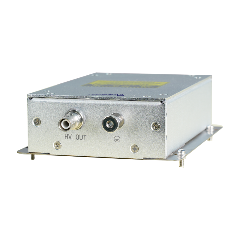
Design and Implementation of High-Voltage Power Supply in High-Voltage Test Bench
1. Introduction
As the core platform for insulation performance testing of electrical equipment, the high-voltage test bench's reliability and accuracy directly affect the safe operation of power systems. As a critical component of the test bench, the high-voltage power supply must achieve stable output and dynamic adjustment under high-voltage and high-current conditions. Its design requires comprehensive consideration of multi-dimensional technical requirements such as electrical parameter matching, electromagnetic compatibility (EMC) characteristics, and system protection mechanisms.
2. Technical Requirement Analysis of High-Voltage Power Supply
In high-voltage test scenarios, the power supply must meet the following core technical specifications:
1. Output Characteristics: The voltage range typically covers 0-500kV (adjustable), with a ripple coefficient ≤1% to ensure test voltage stability; the current output capability should match the test sample capacitance, with a typical value of 0-100mA for continuous adjustment.
2. Dynamic Response: When the test sample breaks down, the power supply must complete overcurrent detection and output shutdown within microseconds to avoid equipment damage.
3. Electromagnetic Compatibility (EMC): Electromagnetic noise generated by the high-voltage circuit must be controlled within the limits of GB/T 17626.2 standards to prevent interference with the control system.
4. Safety Mechanisms: It must integrate multiple protection functions, including overvoltage protection, overcurrent protection, discharge protection, and personal safety interlock devices.
3. Topological Structure Design of High-Voltage Power Supply
(1) Main Circuit Architecture
The classic topology of power frequency transformer step-up + high-voltage rectification and filtering is adopted, with the following specific designs:
Front-stage Voltage Regulation Module: A phase-shifting thyristor voltage regulator is used to achieve continuous adjustment of 0-380V AC power by changing the trigger angle, with a response time ≤200ms.
Step-up Transformer: An oil-immersed insulation structure is employed, with a voltage transformation ratio designed as 1:1000. The rated capacity is configured as 50kVA-200kVA according to test requirements, and the winding uses a graded insulation process to withstand impulse voltages.
High-Voltage Rectification Unit: A bridge silicon stack rectification circuit is used, combined with a high-voltage filter capacitor (with a capacity of 10nF-100nF), to convert alternating high voltage into DC high voltage with a controllable ripple coefficient.
(2) Control and Protection System
1. Closed-Loop Control Strategy: A PI controller is used to achieve closed-loop regulation of the output voltage. The sampling signal is obtained through a high-precision resistor voltage divider (with a voltage division ratio of 1000:1), and the control accuracy reaches ±0.5%.
2. Overcurrent Protection Design: High-frequency current sampling is realized based on a Rogowski Coil. When a current mutation (di/dt>10A/μs) is detected, the thyristor fast shutdown circuit is triggered, with a cut-off time ≤1μs.
3. Human-Machine Interface: A touchscreen operation terminal is integrated to display voltage and current waveforms and test time in real time, supporting preset test parameters and data storage functions.
4. Key Technical Challenges and Solutions
1. Insulation Structure Optimization
High-voltage components adopt epoxy resin casting technology. The air gap distance is designed according to GB 311.1 standards. In environments below 1000m above sea level, the minimum air gap for the 120kV voltage level is 150mm. The electrode shape is optimized through electric field simulation (using finite element analysis software) to reduce local field strength concentration.
2. Electromagnetic Interference Suppression
A double-layer shielding technology is used: the inner layer uses a copper mesh to shield the high-voltage electric field, and the outer layer uses ferromagnetic materials to suppress magnetic field coupling; control cables use twisted shielded wires with an impedance matching of 120Ω to reduce common-mode interference.
3. Temperature Rise Control
The transformer winding uses a combination of Nomex insulation paper and high thermal conductivity silicone grease, coupled with a forced oil circulation cooling system, to control the hot spot temperature below 105°C (F-class insulation standard). Through heat flow simulation analysis, the oil circuit distribution is optimized to improve heat dissipation efficiency.
5. Test Verification and Performance Evaluation
The power supply system was integrated into a high-voltage test bench, and the following key data were obtained through testing:
Voltage Regulation Rate: When the load changes from 0 to the rated value, the output voltage fluctuation ≤0.8%.
Transient Response: During simulated test sample breakdown, the overcurrent protection action time was 0.8μs, and the time for the output voltage to drop to 10% of the rated value was 5μs.
EMI Test: In the 30MHz-1GHz frequency band, the radiation noise peak was below 40dBμV/m, meeting industrial-grade EMC standards.
6. Conclusion
The design and implementation of a high-voltage power supply are core technical links in the construction of a high-voltage test bench, and its performance directly determines the accuracy of test results and equipment safety. By selecting a reasonable topology, adopting precise control strategies, and improving protection mechanisms, a high-reliability high-voltage power supply system can be constructed, providing a solid technical support for the insulation performance evaluation of power equipment. In the future, with the application of wide-bandgap semiconductor devices, the miniaturization and efficiency improvement of high-voltage power supplies will become important development directions.
