


Key Technologies and Applications of Over-Current Protection Design in Electron Beam High-Voltage Power Supplies
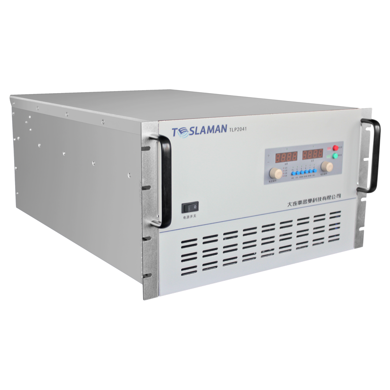
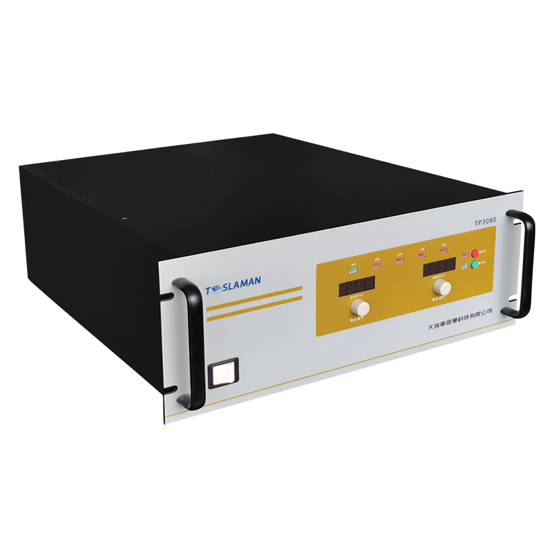
Electron beam high-voltage power supplies are widely used in industrial processing, medical equipment, and scientific research facilities. Their core requirement is stable operation under high-voltage (typically kilovolts to tens of kilovolts) and high-current pulse conditions. However, electron beam devices may generate instantaneous over-currents of tens of kiloamperes during abnormal conditions such as load short circuits or arc discharges, leading to power device burnout or system failure. Thus, over-current protection design must balance response speed, reliability, and low power consumption, serving as a critical safeguard for high-voltage power systems.
1. Technical Challenges in Over-Current Protection
• Response Time Limits: Traditional solutions (e.g., MCU-based software processing) exhibit microsecond-level delays, insufficient for nanosecond-scale current spikes during high-voltage short circuits.
• Power-Accuracy Trade-off: Sampling resistor power loss scales with the square of current. Milliohm-level resistors are essential for high-current scenarios, but tiny signals require high-precision amplification circuits.
• Noise Immunity: Switching noise in high-voltage power supplies can interfere with detection signals, increasing false-trigger risks.
2. Hardware-Software Collaborative Protection Architecture
Modern electron beam power supplies adopt hierarchical protection:
• Hardware-Level Fast Shutdown:
• Current Sensor + Trigger Circuit: Hall sensors or current transformers are connected in series between switching tubes (e.g., IGBTs) and loads. When current exceeds the threshold, the trigger circuit directly drives transistors to pull down the gate voltage, forcing shutdown within 100 nanoseconds.
• Voltage Suppression Devices: TVS diodes in parallel with the gate absorb voltage spikes, preventing device breakdown.
• Software-Level Fault Management:
• Secondary Current Sampling: A low-side current detection circuit (e.g., differential amplifier) transmits signals to the control unit to calculate RMS values and identify sustained over-current.
• Intelligent Recovery: Automatic restart after fault clearance, avoiding repeated triggers.
3. Low-Power and High-Precision Design
• Milliohm-Level Sampling Resistors: Use low-temperature-drift alloy resistors (e.g., manganin) paired with differential amplifiers (e.g., INA-series instrumentation amplifiers) to amplify microvolt signals, reducing power loss while improving SNR.
• Dynamic Threshold Adjustment: Adapt over-current thresholds based on temperature and operational states (e.g., pulse duty cycle) to prevent false triggers at low temperatures or delayed protection at high temperatures.
4. Key Circuit Design Principles
• Isolation Design:
Optocouplers or isolation transformers transmit drive signals, blocking common-mode noise to ensure control unit safety.
• Fault Diagnosis and Redundancy:
Add audible/visual alarms to indicate fault types (e.g., over-current/over-voltage); parallel multi-switch structures allow derated operation if a single device fails.
5. Future Development Trends
• Integrated Protection Chips: Combine current detection, comparators, and drive circuits into a single chip to reduce discrete components and enhance reliability (e.g., integrated high/low-side current detection ICs).
• Adaptive Algorithms: AI-driven over-current risk prediction, e.g., training short-circuit probability models using historical data for preemptive protection.
Over-Current Protection Performance Comparison
Protection Tier Response Time Power Consumption Typical Application
Hardware Trigger (Transistor) <100 ns Ultra-low Instantaneous high-current shutdown
Software Control (MCU) 1–10 μs Moderate Sustained over-current management
Traditional Fuse >1 ms High (post-fuse) Low-cost backup protection
--
The over-current protection design for electron beam high-voltage power supplies is a systematic integration of hardware and software. With the adoption of wide-bandgap semiconductors (e.g., SiC devices), future designs will evolve toward nanosecond response, microwatt power consumption, and intelligence, providing a more reliable safety foundation for high-energy electron beam equipment.
Key Technical Indicators:
Instantaneous over-current tolerance: >20 kA/μs
Protection response delay: <200 ns
Standby power consumption: <0.1 W
Operating temperature range: -40°C to +125°C