Load Adaptability of High-Power Adjustable Power Supplies
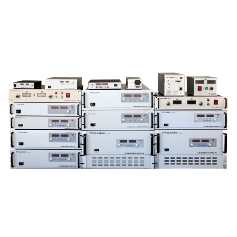
High-power adjustable power supplies (usually referring to rated power ≥10kW) are widely used in scenarios such as electric vehicle testing, high-power industrial equipment drive, and new energy storage. In these scenarios, the load types are diverse (resistive, inductive, capacitive) and the load parameters (current, power) are prone to sudden changes. Therefore, improving load adaptability is the core to ensure the stable operation of the power supply. High-power adjustable power supplies need to realize efficient adaptation to different loads through dynamic response optimization, improvement of protection mechanisms, adaptation of topological structures, and load sharing technology, ensuring stable output voltage and current.
Dynamic response optimization copes with sudden load changes. High-power loads (such as electric vehicle motor controllers) are prone to sudden power changes (such as from 10kW to 50kW) during operation. If the power supply dynamic response is slow, it will lead to large fluctuations in the output voltage, affecting the normal operation of the load. The optimization of dynamic response needs to start from both control algorithm and hardware design: in terms of control algorithm, current mode control is adopted instead of traditional voltage mode control. Current mode control takes the inductor current as the feedback quantity, and the response speed is 3~5 times faster than that of voltage mode control, which can quickly track the load current change; at the same time, feedforward control is introduced to take the load current change rate as the feedforward signal, adjust the power supply output in advance, so that the dynamic response time is shortened to 20μs and the output voltage overshoot is controlled within 3%. In terms of hardware design, the DC bus capacitor capacity is increased (such as parallel connection of 1000μF/450V electrolytic capacitors) to improve the bus voltage stability. When the load changes suddenly, the capacitor can quickly release energy to compensate for the load demand; in addition, high-frequency power semiconductor devices (such as SiC MOSFET) are selected, and the switching frequency is increased to more than 100kHz to reduce control delay and further improve the dynamic response speed.
Perfect protection mechanisms avoid power supply damage caused by load faults. High-power loads may experience faults such as short circuit, overload, and overvoltage during operation. If the power supply has no reliable protection, it will lead to the burnout of power devices. The protection mechanism needs to cover all types of load faults: overcurrent protection adopts "hardware + software" dual protection. At the hardware level, the current is collected through a current sampling resistor (such as a 0.01Ω high-precision resistor). When the current exceeds 1.5 times the rated value, the hardware protection is triggered immediately to cut off the output; at the software level, the current is sampled through ADC, and an overload delay protection is set (such as 1.2 times the rated current for 500ms delay protection) to avoid false triggering of protection by instantaneous inrush current. Short-circuit protection combines a fast fuse (such as 100A/250V) with IGBT overcurrent shutdown. When the load is short-circuited, the fuse blows within 10ms, and the IGBT drive circuit turns off the switching tube immediately to prevent device overcurrent damage. Overvoltage protection is aimed at capacitive loads (such as electrolytic capacitor charging). When the output voltage exceeds 1.2 times the rated value, a pressure relief circuit (such as thyristor pressure relief) is triggered to release the voltage quickly, avoiding damage to the load and power supply. In addition, the protection mechanism should have a self-recovery function. After the load fault is eliminated, the power supply can restart automatically (or manually) without replacing components, improving the operation and maintenance efficiency.
Topological structure adapts to different load types. Different load types (resistive, inductive, capacitive) have different requirements for the output characteristics of the power supply, and appropriate topological structures should be selected: for resistive loads (such as resistance furnaces), the load current and voltage are in the same phase, and the full-bridge phase-shifted topology is sufficient, which has high efficiency and simple control. For inductive loads (such as motors and transformers), the load has energy storage characteristics and will generate back EMF when power is off. A freewheeling diode (such as a fast recovery diode) should be connected in parallel at the power supply output end, and soft switching technology should be adopted to avoid voltage spikes caused by back EMF. For capacitive loads (such as batteries and supercapacitors), the current is large and changes rapidly during charging. The LLC resonant topology is adopted. The LLC topology can stably output current during the constant current charging stage, avoid current impact, and realize soft switching at the same time, reducing loss. For mixed loads (such as carrying both resistive and inductive loads), a multi-level topology (such as a three-level topology) is adopted. The output voltage waveform of the multi-level topology is closer to a sine wave, with low harmonic content, which can reduce interference to the load and improve the load capacity of the power supply. The power supply efficiency is still maintained above 92% under mixed loads.
Load sharing technology realizes multi-power supply parallel loading. When the load power exceeds the rated power of a single power supply (such as a 100kW load), multiple high-power adjustable power supplies need to operate in parallel. At this time, it is necessary to ensure that the load current of each power supply is shared equally to avoid overload of a certain power supply. The load sharing technology adopts the "master-slave control + current sharing bus" scheme: one power supply is selected as the master power supply, and the others are slave power supplies. The master power supply sets the output voltage and current reference. The slave power supplies collect the current signals of the master power supply and other slave power supplies through the current sharing bus, and adopt the droop control algorithm (such as voltage droop coefficient 0.5%/100A) to adjust their own output voltage, so that the current deviation of each power supply is controlled within 5%. In addition, a digital current sharing scheme is adopted to realize communication between power supplies through the CAN bus, share current data in real time, and dynamically adjust the output, improving the current sharing accuracy to within 3%. At the same time, the parallel system should have redundancy function. When a certain power supply fails, the remaining power supplies can automatically share the load to ensure uninterrupted operation of the load and improve system reliability.
Through the above technical means, the high-power adjustable power supply can adapt to resistive, inductive, capacitive, and mixed loads. The load regulation rate (from no-load to full-load) is controlled within 0.5%, the dynamic response time is ≤50μs, the protection mechanism response time is ≤10ms, and the current sharing accuracy of multi-power supply parallel connection is ≤3%, meeting the load requirements of complex scenarios such as electric vehicle testing and industrial high-power equipment drive.
