Design of High-Frequency Transformer for Fusion Additive High-Voltage Power Supply
1. Introduction
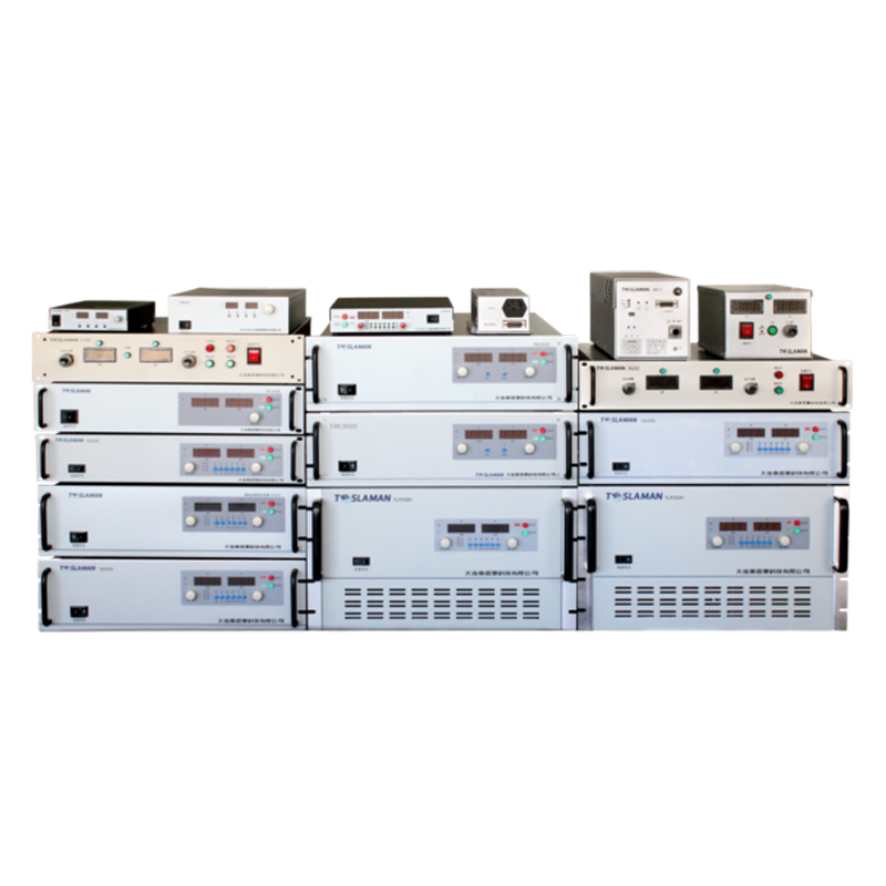
Fusion additive manufacturing technology (such as selective laser melting and electron beam melting) realizes part forming by melting metal powder with high-energy beams. As the energy core of the high-energy beam generating device, the performance of the high-voltage power supply directly affects the forming quality. The high-frequency transformer is a key component of the high-voltage power supply, undertaking the functions of voltage conversion and energy transmission. Its design quality determines the conversion efficiency, volume, and reliability of the power supply. The traditional power frequency transformer cannot meet the requirements of fusion additive equipment for power supply lightweight and high efficiency due to its large volume and high loss. However, the high-frequency transformer can significantly reduce the volume and weight by increasing the working frequency (usually ≥20kHz), and at the same time reduce the copper loss and iron loss. Therefore, carrying out targeted design of the high-frequency transformer for the fusion additive high-voltage power supply has important significance.
2. Key Technologies for High-Frequency Transformer Design
(1) Determination of Topology and Working Parameters
According to the power demand (usually 1kW~10kW) and output voltage level (0kV~80kV) of the fusion additive high-voltage power supply, the phase-shifted full-bridge topology is selected as the main circuit topology of the power supply. This topology has the advantages of low switching loss and small output ripple, which is suitable for high-frequency and high-voltage scenarios. The core working parameters of the high-frequency transformer are determined based on the topology:
1.Working frequency f: Considering the iron loss (increasing with the increase of frequency) and volume (decreasing with the increase of frequency), f=50kHz is selected, at which the iron loss and volume reach a balance;
1.Input voltage Vin: DC bus voltage, determined as 380V according to the power supply design requirements;
1.Output voltage Vout: Determined as 60kV according to the requirements of the electron beam or laser generating device;
1.Rated power P: Determined as 5kW according to the maximum energy demand of the additive equipment;
1.Transformation ratio n: Calculated according to the ideal transformer transformation ratio formula n=Vout/(Vin×D) (D is the duty cycle, ranging from 0.4 to 0.5), and the result is n≈316 (rounded up to 320, with a margin reserved considering the influence of leakage inductance and copper loss).
(2) Core Material Selection and Core Structure Design
The magnetic core is a core magnetic circuit component of the high-frequency transformer, and its material performance directly affects the transformer loss and permeability. Aiming at the characteristics of high frequency, high voltage, and high power of the fusion additive high-voltage power supply, the magnetic core material is high-frequency ferrite material (such as PC44 material), which has the advantages of high saturation magnetic flux density (Bs≥0.45T), low loss (under the conditions of 50kHz and 0.2T, the loss ≤300mW/cm³), and high permeability (μ≥2500), suitable for high-frequency working conditions.
The EE-type magnetic core is selected for the core structure. Compared with the EI-type magnetic core, it has better magnetic circuit symmetry and smaller magnetic leakage; the core size is determined according to the power and loss calculation: first, according to the power formula \(P_{core} = k \cdot f \cdot B_m^{2} \cdot V_{core}\) (k is the material coefficient, B_m is the working magnetic flux density, V_core is the core volume), combined with the allowable iron loss (usually ≤30% of the total loss), the core volume V_core≥200cm³ is calculated; then, according to the standard size series of EE-type magnetic cores, the EE85-type magnetic core (cross-sectional area S=56mm², magnetic path length l=250mm) is selected, which meets the volume and loss requirements.
(3) Winding Design and Insulation Treatment
Winding design needs to take into account copper loss control, insulation performance, and heat dissipation requirements, which is a core difficulty in high-frequency transformer design.
1.Conductor selection: Under high frequency, the conductor has skin effect and proximity effect, which causes the current to concentrate on the conductor surface and increases the copper loss. Multi-strand enameled wire (Litz wire) is used, and the number of strands is determined according to the skin depth calculation: skin depth \(\delta = \sqrt{\frac{\rho}{\pi f \mu_0}}\) (ρ is the resistivity of copper, μ_0 is the vacuum permeability). At 50kHz, δ≈0.2mm, so Litz wire with a strand diameter of 0.18mm is selected, with 100 strands, and the total cross-sectional area S=π×(0.18/2)²×100≈2.54mm², which meets the current-carrying capacity requirement (rated current I=P/Vin≈13.2A, current density J=I/S≈5.2A/mm², within the allowable range).
1.Winding structure: A layered and segmented winding method is adopted. The primary winding (low-voltage side) and the secondary winding (high-voltage side) are arranged in layers to avoid high-voltage breakdown; the secondary winding has a high voltage (60kV), so it is wound in segments, and the voltage of each segment is controlled within 5kV to reduce the voltage difference between segments; at the same time, a shielding layer (made of copper foil) is set between the primary and secondary windings to reduce magnetic leakage and electromagnetic interference.
1.Insulation design: The high-voltage side winding needs to meet strict insulation requirements, and a multi-layer insulation structure is adopted: the conductor insulation uses polyimide enameled wire with a temperature resistance level of class H (≥180℃); the inter-layer insulation uses polyimide film (thickness 0.1mm, breakdown voltage ≥10kV); the insulation between the winding and the magnetic core uses epoxy glass cloth tube (thickness 1mm, breakdown voltage ≥20kV); at the same time, the winding creepage distance (≥5mm/kV) is controlled to ensure no breakdown risk under 60kV high voltage.
(4) Leakage Inductance and Distributed Capacitance Control
Excessive leakage inductance will cause voltage spikes of the switching tube, and excessive distributed capacitance will affect the voltage waveform at high frequency. Therefore, measures need to be taken to control leakage inductance and distributed capacitance.
1.Leakage inductance control: A tight winding method is adopted to ensure that the winding is closely attached to the magnetic core; the primary and secondary windings are wound in a staggered manner (after winding 1 layer of the primary, 1 segment of the secondary is wound, alternately in sequence) to reduce the magnetic resistance between the windings; the winding layout is optimized through finite element simulation (such as ANSYS Maxwell), and the simulation results show that the leakage inductance can be controlled within 5μH (≤5% of the primary inductance).
1.Distributed capacitance control: The secondary winding is wound in segments, and a grounded shielding layer is set between each segment to reduce the distributed capacitance between segments; insulation materials with low dielectric constant (such as polytetrafluoroethylene, dielectric constant ε_r≈2.1) are selected to reduce the distributed capacitance of the insulation layer; the winding spacing is optimized through simulation to control the distributed capacitance within 100pF, avoiding resonance at high frequency.
(5) Heat Dissipation Design
The copper loss and iron loss generated by the high-frequency transformer during operation will cause temperature rise. If heat dissipation is not timely, it will affect the insulation performance and service life. An integrated heat dissipation structure is adopted: the magnetic core and winding are immersed in transformer oil (high-voltage resistant and high thermal conductivity mineral oil, breakdown voltage ≥100kV, thermal conductivity ≥0.15W/(m·K)) to take away heat through oil cooling; at the same time, heat dissipation fins are set on the transformer shell to increase the heat dissipation area; the shell material is aluminum alloy to improve the thermal conductivity. Through thermal simulation analysis, under the rated power, the maximum temperature of the transformer is ≤100℃, meeting the temperature resistance requirements of the insulation material.
3. Design Verification and Application Effects
(1) Performance Test
The designed high-frequency transformer was tested for performance, and the test results are as follows:
1.Transformation ratio: The actual test transformation ratio is 318, with a deviation of ≤1% from the design value of 320, meeting the voltage conversion requirements;
1.Loss: Under the rated power and 50kHz working condition, the iron loss is 120W, the copper loss is 180W, the total loss is 300W, and the conversion efficiency is ≥94% (η=P/(P+total loss)≈5000/(5000+300)≈94.3%);
1.Leakage inductance: The tested leakage inductance is 4.2μH, which is less than the design allowable value of 5μH;
1.Insulation performance: A withstand voltage test was carried out at 1.5 times the rated voltage (90kV) for 1 minute, with no breakdown or flashover, and the insulation performance is qualified.
(2) Application Effects
After the high-frequency transformer is applied to the fusion additive high-voltage power supply, the overall performance of the power supply is significantly improved: the power supply volume is reduced by 60% compared with the traditional power frequency power supply, and the weight is reduced by 50%, meeting the lightweight requirements of the additive equipment; the power supply conversion efficiency is increased from 85% (traditional) to 92%, reducing energy consumption; in the fusion additive printing experiment, the power supply output voltage ripple coefficient is ≤0.5%, ensuring stable laser energy, uniform molten pool shape of the printed part, dimensional accuracy error ≤0.2mm, and qualified mechanical performance.
4. Conclusion
The high-frequency transformer of the fusion additive high-voltage power supply solves the problems of large volume, high loss, and poor insulation performance of the traditional transformer through reasonable magnetic core selection, winding design, insulation treatment, and heat dissipation optimization, meeting the requirements of fusion additive equipment for high efficiency, lightweight, and high reliability of the power supply. This design scheme provides key support for the performance improvement of the fusion additive high-voltage power supply. In the future, new magnetic core materials (such as amorphous alloys) and advanced winding processes can be further explored to further reduce losses and improve power density.
