Implementation of Remote Parameter Setting and Monitoring for High-Power Adjustable Power Supplies
Introduction
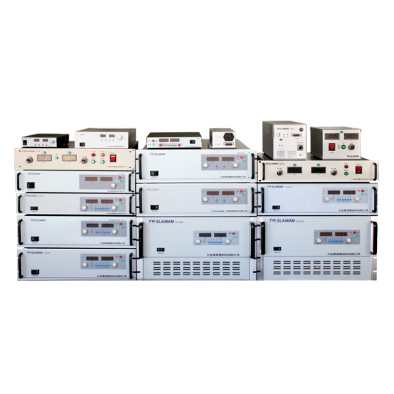
High-power adjustable power supplies are widely used in industrial fields such as metallurgy, electrolysis, and energy storage systems. In these applications, power supplies are often installed in harsh environments (e.g., high temperature, high humidity, and strong electromagnetic interference), and manual on-site parameter setting and monitoring not only increase the labor intensity of operators but also bring safety risks. Therefore, realizing remote parameter setting and real-time monitoring of high-power adjustable power supplies is of great significance for improving operation efficiency, ensuring system safety, and reducing maintenance costs.
Core Technical Challenges
The key challenges in the implementation process include three aspects. First, the high-power power supply has large current and voltage output, and the electromagnetic interference (EMI) generated during operation is strong, which easily affects the stability of remote communication signals, leading to data transmission errors or signal loss. Second, the remote control system needs to have high real-time performance. For example, in the electrolysis process, the load current changes rapidly, and the remote system must adjust the power supply parameters within milliseconds to avoid overvoltage or overcurrent. Third, the remote system needs to manage multiple power supplies in parallel, requiring functions such as address identification, data synchronization, and centralized control, which increases the complexity of the system.
Implementation Scheme
Hardware Architecture Design
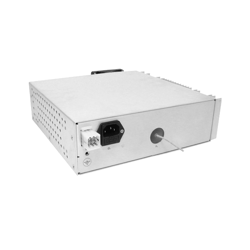
The hardware system adopts a three-layer structure: field layer, communication layer, and monitoring layer. In the field layer, an embedded controller (based on a 32-bit ARM Cortex-M7 core) is integrated into the high-power adjustable power supply. The controller is equipped with isolated analog-to-digital converters (ADCs) and digital-to-analog converters (DACs) to realize high-precision sampling of output voltage/current and accurate control of power devices. To suppress EMI, the controller uses optical isolation modules for signal transmission between the power circuit and the communication circuit, and adds surge protectors at the communication interface to prevent voltage spikes from damaging the equipment.
In the communication layer, a dual-communication mode of Ethernet (Modbus TCP protocol) and industrial wireless (LoRaWAN protocol) is adopted. Ethernet is used for fixed-site, high-speed data transmission (transmission rate up to 100Mbps) to realize real-time parameter adjustment and large-volume data upload (e.g., historical operation data). LoRaWAN is used for mobile or remote sites with difficult wired deployment, with a communication distance of up to 5km and strong anti-interference ability, ensuring that the monitoring signal is not interrupted in harsh industrial environments.
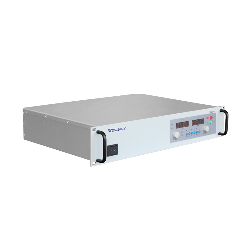
In the monitoring layer, an industrial computer is used as the monitoring host, and a human-machine interface (HMI) is developed based on Qt. The HMI can display the real-time output voltage, current, power, and working status of each power supply in the form of numbers and curves. It also supports remote setting of parameters such as output voltage, current limit, and protection threshold, and has functions such as parameter storage, historical data query, and alarm notification (e.g., overvoltage, overcurrent, and overtemperature alarms are sent to the operator's mobile phone via SMS or APP).
Software Algorithm Optimization
To improve the real-time performance of remote control, a priority-based data transmission algorithm is designed. The data is divided into three levels: emergency data (e.g., overcurrent alarm), control data (e.g., parameter adjustment commands), and monitoring data (e.g., historical current curves). The communication system transmits data according to the priority, ensuring that emergency data and control data are transmitted within 10ms, meeting the real-time control requirements of high-power loads.
In addition, a data verification mechanism based on cyclic redundancy check (CRC) is added. Each data packet sent by the monitoring host or the power supply controller contains a CRC check code. After receiving the data, the receiving end recalculates the CRC code and compares it with the received one. If they are inconsistent, the data is discarded and a retransmission request is sent, reducing the data transmission error rate to less than 10^-6.
Application Verification
In a large-scale electrolytic aluminum plant, 20 high-power adjustable power supplies (each with an output voltage of 0-1000V and a current of 0-5000A) are connected to the remote monitoring system using the above scheme. The actual operation shows that the system can realize remote parameter setting (voltage adjustment response time < 5ms) and real-time monitoring (data update frequency 10Hz). During a 3-month continuous operation, the system has no communication failure, and the overcurrent and overvoltage alarms are accurately sent within 100ms, avoiding 3 potential equipment damage accidents. Compared with the traditional manual on-site operation, the operation efficiency is increased by 40%, and the maintenance cost is reduced by 25%.
Conclusion
The remote parameter setting and monitoring system of high-power adjustable power supplies based on the three-layer hardware structure and optimized software algorithms can effectively solve the problems of strong EMI, high real-time requirements, and multi-device management in industrial applications. It improves the operation safety and efficiency of power supplies and provides a feasible solution for the intelligent management of high-power electrical systems.
