Ampoule Visual Inspection Synchronized High Voltage Trigger
In the pharmaceutical and biotechnology industries, the integrity of parenteral product containers, such as glass ampoules, is critical for ensuring sterility and safety. Automated visual inspection systems are employed to detect defects like cracks, holes, or inclusions in the ampoule body and seal. A highly effective technique for leak detection in sealed ampoules involves applying a high-voltage potential across the container to stimulate a discharge in the presence of a breach. The synchronization of this high-voltage pulse with the precise moment of visual imaging and the ampoule's mechanical positioning is a complex mechatronic challenge. This examination details the application-specific requirements for the high-voltage trigger power supply within such synchronized inspection systems.
The principle of electrical leak testing (or dielectric withstand testing) for ampoules exploits the difference in dielectric strength between glass and air. A intact glass ampoule acts as a robust insulator. When a sufficiently high voltage is applied between an external electrode and an internal electrode (or a conductive fluid inside), no current flows. However, if a microscopic crack or pinhole breach exists, it creates a localized path of lower dielectric strength. At a critical voltage, the air within the defect ionizes, resulting in a transient capacitive discharge or a sustained arc. The detection of this current flow, often just microamperes initially, signals a failure.
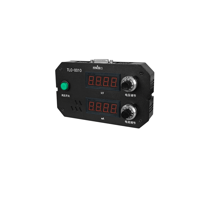
The role of the high-voltage power supply in this inspection station is not to provide continuous DC, but to generate a precisely timed, shaped, and magnitude-controlled high-voltage pulse. This pulse must be applied at the exact moment when the ampoule is in the correct inspection position, aligned between the electrodes, and simultaneously when the high-speed camera is ready to capture an image. The synchronization of these three events—mechanical positioning, imaging trigger, and high-voltage pulse—is the core of the system's design.
The triggering mechanism is paramount. The power supply must accept a low-voltage logic trigger signal (e.g., a TTL pulse) from the system's master programmable logic controller (PLC) or vision computer. Upon receiving this signal, the supply must generate the high-voltage output with a consistent, minimal, and predictable delay (jitter). Jitter of even a few microseconds can be problematic. If the high voltage fires too early or too late relative to the camera's exposure, the resulting discharge (for a defective ampoule) might not be captured in the image, or the image might be taken before the discharge occurs. Therefore, the internal switching circuitry of the power supply, whether based on solid-state switches like MOSFETs/IGBTs or triggered spark gaps, must be designed for ultra-low jitter, often in the nanosecond to low microsecond range.
The waveform characteristics of the pulse are critical for both detection sensitivity and to prevent damage to good ampoules. A common approach is to use a steadily rising ramp voltage. The voltage increases until either a predetermined threshold is reached (pass) or a discharge is detected (fail). The power supply must control the slew rate (dV/dt) of this ramp accurately. Too fast a rise might cause a flashover across the outer surface of a good ampoule due to contaminants, yielding a false positive. Too slow a rise might not excite a subtle defect, yielding a false negative. The output stage must be linear and well-damped to avoid overshoot or ringing on the waveform, which could also cause unintended breakdowns.
Integration with the detection circuitry is intimate. The high-voltage power supply is typically paired with a sensitive picoammeter or current detection circuit. The moment a discharge current is detected, the system must react instantly. Often, the response is to immediately clamp or divert the high voltage to protect the ampoule from excessive energy input and to provide a clear digital fault signal. This means the power supply's control loop must react to an external fault signal even faster than its normal trigger response. Some designs integrate the current detection and voltage control into a single feedback unit, allowing for arc suppression features similar to those in coating power supplies, but optimized for much lower current levels and different time scales.
The system must also account for variable capacitive loading. Different ampoule sizes and shapes present different capacitances to the electrode system. The high-voltage pulse generator must be designed to deliver its specified voltage ramp into a range of capacitive loads without distortion or excessive current demand. This requires careful output stage design with adequate current sourcing capability and stability analysis across the expected load range.
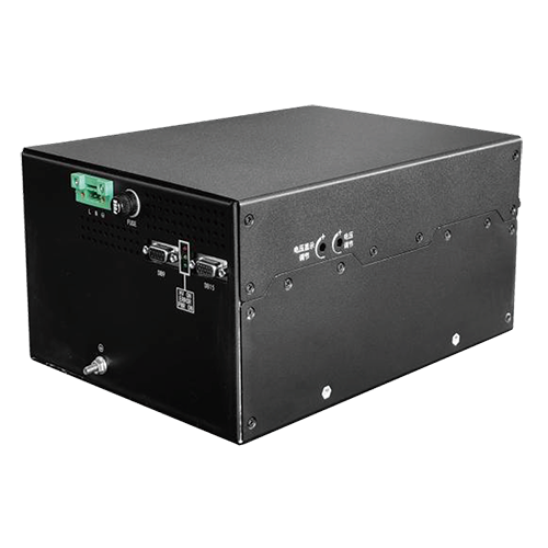
Furthermore, reliability and safety are non-negotiable. An inspection system may test hundreds of thousands of ampoules. The high-voltage trigger system must perform consistently over this lifecycle. Redundancy in detection circuits and thorough self-test routines are common. Safety interlocks ensure the high voltage is only enabled when the inspection chamber is securely closed and the ampoule is correctly positioned. The power supply itself must be housed in an interlocked enclosure with proper grounding and discharge mechanisms.
In essence, the high-voltage trigger supply in an ampoule inspection system is a precision timing instrument and a sensitive detection probe combined. Its value lies not in its kilovolt output alone, but in its microsecond-precision triggerability, its clean and controllable waveform generation, its seamless handshake with current detection and vision systems, and its unwavering reliability. By providing a perfectly synchronized electrical stimulus, it enables the reliable and automated discrimination of hermetically sealed containers from defective ones, forming a critical barrier in ensuring the sterility and safety of injectable medicines.