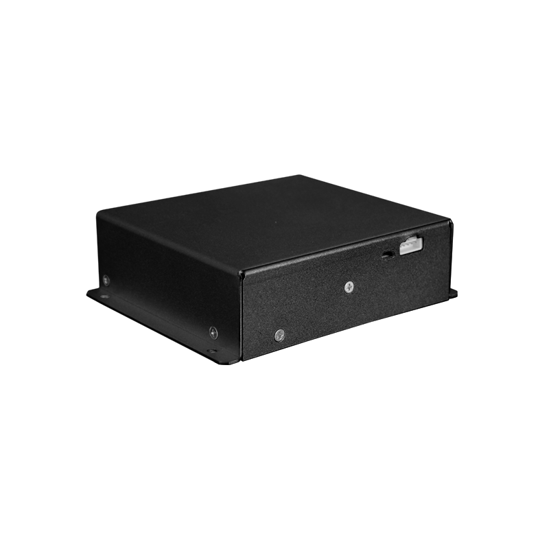
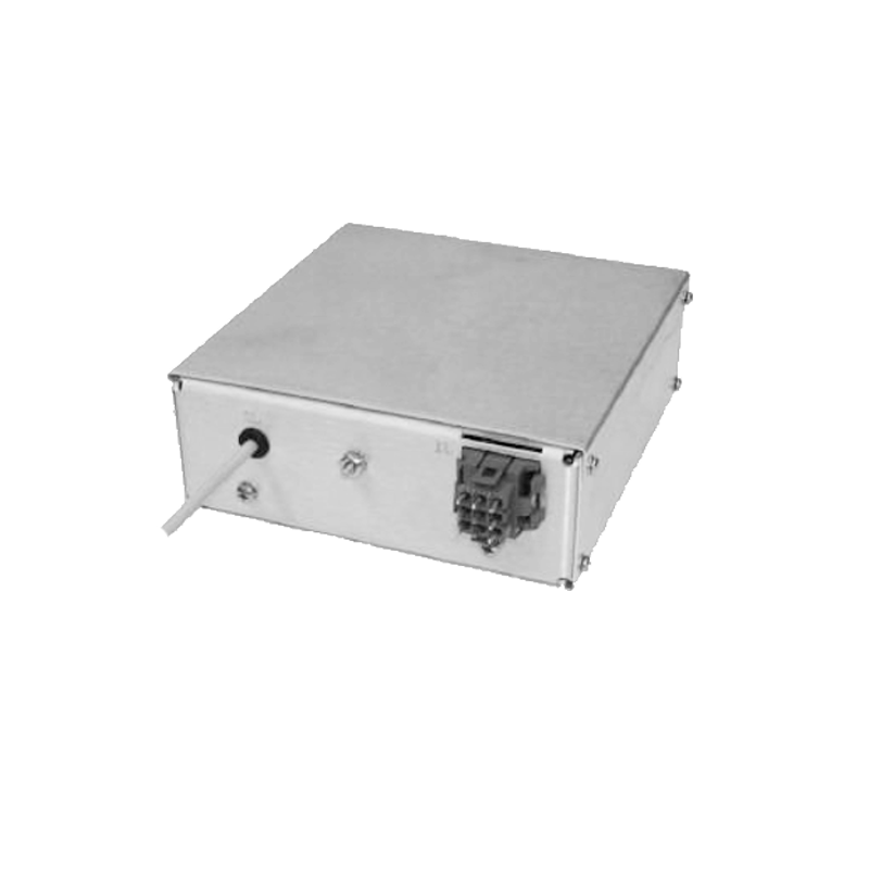
Vacuum Coating Arc Source Evaporation High-Voltage Ignition Power Supply
Cathodic arc evaporation is a powerful PVD technique used to deposit extremely dense, well-adhered coatings, such as titanium nitride or diamond-like carbon. The process is initiated by striking a high-current, low-voltage arc on the surface of a cathode target. However, initiating this arc in a high vacuum, where the gap between the cathode and a trigger electrode is an excellent insulator, requires a precisely controlled high-voltage pulse. This ignition power supply is a specialized, critical subsystem whose reliability and precision directly determine process start-up success, target utilization, and the avoidance of macro-particle generation.
The fundamental task is to create a transient conductive path across a vacuum gap of several millimeters. This is achieved not by a continuous high voltage, but by a very short, high-amplitude voltage pulse with an extremely fast rise time. Typical parameters are a pulse of 10-30 kV, with a rise time of tens of nanoseconds and a duration of a few microseconds. This pulse is applied between the cathode (which is at ground or a negative potential for the main arc) and a small trigger electrode placed very close to the cathode surface. The fast-rising high voltage creates an intense electric field at the tip of the trigger electrode, causing field emission of electrons. These electrons are accelerated across the small gap, striking the cathode and generating a small, localized plasma from the cathode material through electron bombardment. This initial plasma, created by the high-voltage pulse, provides the conductive bridge that allows the main, high-current, low-voltage arc power supply (typically 20-40 V, 50-200 A) to establish its discharge.
The design of this ignition supply is centered on generating this specific pulse shape reliably, thousands of times, without failure. A common topology is a pulse transformer driven by a capacitive discharge circuit. A low-voltage capacitor (charged to 300-1000 V) is switched by a fast semiconductor switch (like a thyristor or a specially rated MOSFET) into the primary of a step-up pulse transformer. The transformer's turns ratio, its leakage inductance, and its winding capacitance are carefully engineered to produce the desired high-voltage pulse shape on the secondary. The extremely fast rise time is achieved by minimizing all parasitic inductances in the discharge loop and using a transformer core material suitable for very short pulse operation.
Reliability is the paramount concern. A failed ignition attempt can leave the main arc supply connected to an open circuit, potentially damaging its output stage. Therefore, the ignition supply incorporates robust diagnostics and sequencing logic. A typical sequence is: 1) The main arc supply is enabled but held at zero output. 2) The ignition supply fires its high-voltage pulse. 3) A current sensor on the trigger circuit detects the flow of the small ignition current (amperes), confirming plasma formation. 4) This confirmation signal is sent to the main arc supply, which immediately ramps its current to the setpoint, transferring the arc from the trigger to the main cathode circuit. 5) The trigger electrode is then electrically disconnected or biased to a potential that discourages continued arcing at that spot, encouraging the main arc to move randomly across the cathode surface.
The ignition supply must also be adaptive. As the cathode erodes, the physical gap between the trigger and the cathode surface changes. An ideal ignition system compensates for this. Some advanced designs measure the impedance of the trigger-cathode gap just before firing. If the gap is too large (indicating excessive erosion), the ignition supply can increase its stored energy or pulse amplitude to ensure a successful strike. Conversely, if the gap is very small, it can reduce the pulse energy to prevent excessive local melting of the cathode, which generates macro-particles.
Integration with the vacuum system and safety are critical. The ignition pulse generator is usually housed in a separate, shielded module to prevent electromagnetic interference with sensitive film thickness monitors or other electronics. All cables to the arc source are coaxial and shielded to minimize radiated noise. High-voltage connectors are designed for vacuum feedthroughs, with proper creepage distances to prevent surface tracking. The system includes interlocks that prevent ignition attempts if the chamber pressure is too high (risking a glow discharge instead of an arc) or if cooling water flow to the source is insufficient. In high-power, multi-arc systems, the timing of ignition for each source may be staggered to prevent simultaneous high-current inrushes from overloading the facility's electrical supply. Thus, the humble ignition power supply, through its nanosecond-scale precision, enables the robust and repeatable initiation of one of the most energetic and useful deposition plasmas in thin-film technology.