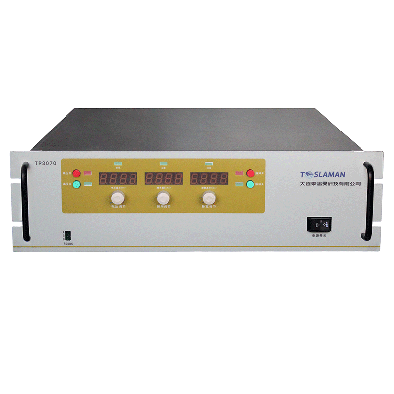
High-Voltage Thinning for Transmission Sample Preparation in Focused Ion Beam Systems
The preparation of electron-transparent samples for transmission electron microscopy is a delicate and precise art. The focused ion beam system has become the tool of choice for this task, capable of milling site-specific lamellae with nanometer precision. The final and most critical step in this process is the thinning of the lamella to a thickness of less than 100 nanometers, a task that relies on a high-voltage ion column operating at typical energies of 30 keV. After fifty years of working with high-voltage systems, I can attest that the quality of the final TEM image is directly dependent on the stability and precision of the high-voltage supplies that govern the ion beam used for this final thinning.
The ion column in a FIB is a complex optical instrument. It generates a beam of gallium ions, accelerates them through a high potential, and then focuses them onto the sample using a series of electrostatic lenses. For the final thinning pass, the goal is to remove the last few tens of nanometers of material with minimal damage to the delicate lamella. This requires an ion beam with a very small spot size and a very low current. Achieving this pushes the high-voltage supplies to their limits.
The first and most obvious requirement is the stability of the accelerating voltage. The energy of the ions is directly determined by this voltage. Any fluctuation in the accelerating potential changes the ion's velocity and, consequently, its focusing properties. The electrostatic lenses are voltage-driven devices; their focusing power is a function of the applied potential. If the accelerating voltage drifts, the entire optical system goes out of alignment, and the beam spot on the sample will blur and move. For thinning a lamella to 50 nanometers, a beam movement of even 10 nanometers can be catastrophic, leading to a non-uniform thickness or even piercing the sample. Therefore, the high-voltage supply for the ion source and column must have stability in the parts-per-million range over the duration of the thinning process, which can last for many minutes.
Beyond the accelerating voltage, the voltages applied to the various lenses in the column are equally critical. A modern FIB column may have a condenser lens, an objective lens, and various deflectors and stigmators. Each of these elements requires its own high-voltage supply, typically in the kilovolt range, with precision and stability to match the main accelerator. These supplies must be perfectly matched and tracked. For example, the ratio between the lens voltage and the accelerating voltage must be held constant to maintain focus as the beam energy is changed. This requires a sophisticated, high-precision reference and divider network that is common to all the supplies in the column.
The process of thinning itself often involves scanning the beam in a precise pattern to mill away the material. This scanning is achieved by applying ramped voltages to the deflector plates. The linearity and accuracy of these deflection ramps are paramount. A non-linear ramp will cause the beam to dwell longer in some areas than others, leading to a non-uniform mill. The high-voltage amplifiers that generate these scanning waveforms must have exceptional linearity and be free of hysteresis. They must also be fast enough to allow for rapid scanning, but with a settling time that ensures the beam is stable at each pixel before the mill begins.
A significant challenge in FIB thinning is the phenomenon of beam drift, often caused by charging of the sample or the surrounding stage. As the ion beam strikes the insulating lamella, it can implant charge, creating a local electric field that deflects the beam. This causes the milling pattern to slowly shift over time, ruining the uniformity of the thin area. To combat this, some advanced FIB systems employ a drift correction routine. This involves periodically taking a rapid, low-dose image of the sample, cross-correlating it with a reference image to determine the drift, and then applying a correcting offset voltage to the beam deflectors. This closed-loop control requires the high-voltage deflection supplies to respond instantly to the correction signal, adding a precise offset to the scanning waveform without introducing any transients.
The final thickness of the lamella is often monitored in real-time using the scanning electron microscope that is integrated into most modern FIB systems. The SEM images the lamella from the side, allowing the operator to see its thickness. This visual feedback is used to determine when to stop the milling. The operator's command to stop must be translated into an immediate shutdown of the ion beam. This requires the high-voltage supply to the ion source to be gated off almost instantaneously. A slow shutoff would result in a few extra nanoseconds of milling, which could be the difference between a perfect sample and one that is too thin.
In conclusion, the preparation of a TEM sample using a FIB is a symphony of high-voltage precision. The accelerating voltage, the lens voltages, the deflection voltages, and the blanking voltage must all work in perfect harmony to deliver a stable, focused beam to the sample. Any imperfection in any of these supplies will be magnified and transferred to the final lamella, potentially rendering it useless for high-resolution imaging. The unsung heroes of every beautiful TEM image are the ultra-stable, ultra-precise high-voltage power supplies that made the sample preparation possible, a fact that is deeply appreciated by those of us who have spent a lifetime designing and building them.