Heat Dissipation and Shielding for High Power RF Power Supply and High Voltage Power Supply in Shared Cabinet
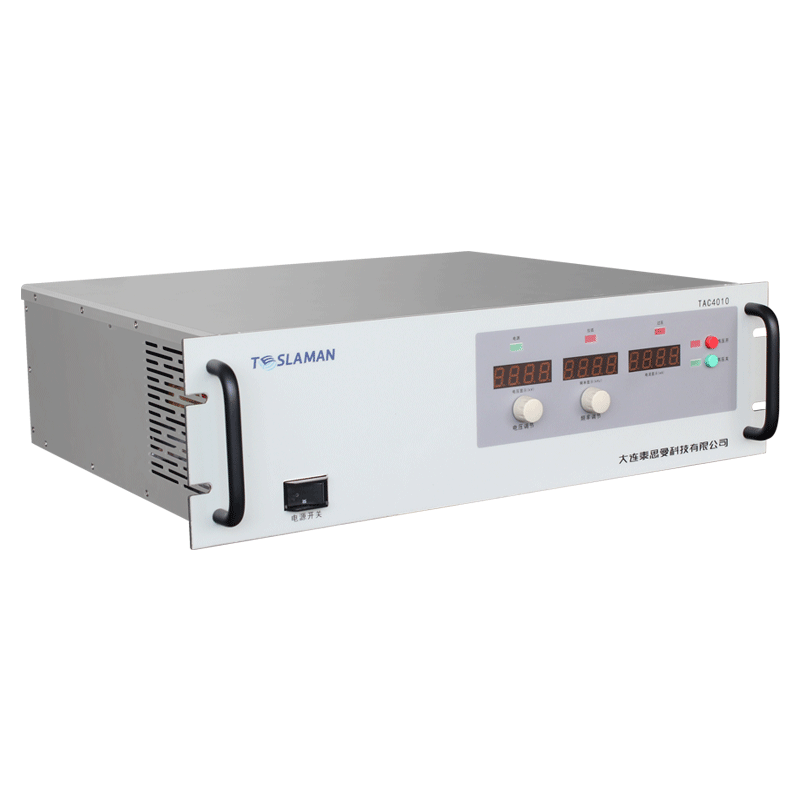
Modern electronic systems often integrate multiple power sources within a single enclosure to reduce size and improve integration. High power radio frequency power supplies and high voltage power supplies may share a cabinet in applications such as plasma processing, broadcast transmitters, and medical equipment. The co-location presents challenges for both thermal management and electromagnetic compatibility. Heat dissipation must remove the combined thermal load while shielding must prevent interference between the systems. Understanding these design challenges enables successful integration.
The electrical requirements for integrated power systems depend on the specific application. RF power supplies may operate at frequencies from megahertz to gigahertz with power levels from hundreds to thousands of watts. High voltage power supplies may operate at tens to hundreds of kilovolts with various current requirements. Both systems must operate reliably in close proximity. The integration must not compromise the performance of either system.
Thermal load analysis determines the cooling requirements. The total heat dissipation is the sum of both power supply losses. The heat distribution within the cabinet affects the cooling approach. Hot spots must be identified and addressed. The thermal design must maintain component temperatures within specifications. The cooling system must handle the combined thermal load.
Airflow management is critical for effective cooling. Forced air cooling is common for cabinet installations. The airflow must reach all heat-generating components. Airflow paths must be designed to avoid recirculation. The fan placement affects the cooling effectiveness. The airflow must not create acoustic noise problems. The cooling design must be practical for maintenance.
Thermal isolation between systems may be necessary. The RF power supply may have different temperature limits than the high voltage supply. Thermal barriers can prevent heat transfer between systems. Separate cooling zones can maintain different temperatures. The thermal isolation must not compromise the overall integration. The thermal design must consider both systems.
Electromagnetic interference is a major concern for co-located systems. The RF power supply generates strong electromagnetic fields. The high voltage supply may be sensitive to RF interference. The high voltage switching may generate conducted and radiated noise. The RF system may be sensitive to switching noise. The shielding must protect both systems from interference.
Shielding design principles involve containing and excluding electromagnetic fields. Conductive enclosures attenuate electromagnetic fields. The shielding effectiveness depends on material conductivity and thickness. Seams and openings can compromise shielding effectiveness. Gaskets ensure electrical continuity at seams. The shielding design must address the relevant frequency range.
Internal shielding partitions separate the systems. Metal barriers between the RF and high voltage sections reduce coupling. The partition must be properly grounded to be effective. Cable penetrations through the partition must be filtered. The partition must not interfere with thermal management. The internal shielding must be comprehensive.
Cable routing affects electromagnetic coupling. Cables can act as antennas for RF interference. Cables can conduct interference between systems. Cable separation reduces coupling. Shielded cables contain electromagnetic fields. Cable routing must be designed with EMC as a primary consideration. The cable design must support both systems.
Filtering at interfaces prevents interference propagation. Power line filters prevent conducted interference. Signal line filters protect sensitive circuits. The filter design must be appropriate for the interference frequencies. The filters must not affect the normal operation of either system. The filtering must be comprehensive at all interfaces.
Grounding design affects both safety and EMC. Safety grounding protects personnel from electrical hazards. EMC grounding provides reference for shielding. Ground loops can cause interference problems. The grounding scheme must balance multiple requirements. The grounding must be properly implemented throughout the system.
Testing and verification validate the integration. Thermal testing verifies that temperatures remain within limits. EMC testing verifies that interference is controlled. Functional testing verifies that both systems operate correctly. The testing must cover all operating conditions. The validation must demonstrate successful integration.
Maintenance access must be practical for both systems. The integration must not prevent maintenance of either system. Access panels must be provided for service. The layout must allow component replacement. The maintenance procedures must be documented. The integration must support long-term maintenance.
Applications of integrated power systems include plasma processing equipment, broadcast transmitters, and medical imaging systems. Each application has specific requirements for thermal management and electromagnetic compatibility. The integration design must support the specific application requirements.