Noise Suppression of High Voltage Power Supply for Scanning Electron Microscope Backscattered Electron Detector
Scanning electron microscopy provides high-resolution imaging of surfaces through the interaction of a focused electron beam with the sample. Backscattered electron detectors capture electrons that are scattered back from the sample surface, providing information about composition and topography. The high voltage power supply that biases the detector must exhibit extremely low noise to preserve the signal integrity and achieve optimal image quality.
Backscattered electrons are primary beam electrons that have undergone elastic scattering interactions with atomic nuclei in the sample. These electrons retain a significant fraction of their incident energy and escape from the sample surface. The backscattered electron coefficient depends on the atomic number of the sample material, making backscattered electron imaging sensitive to compositional variations. The detector converts the electron signal into an electrical signal that forms the image.
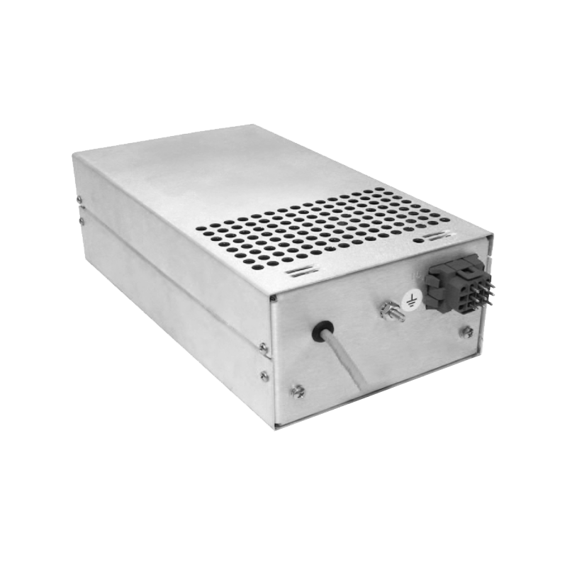
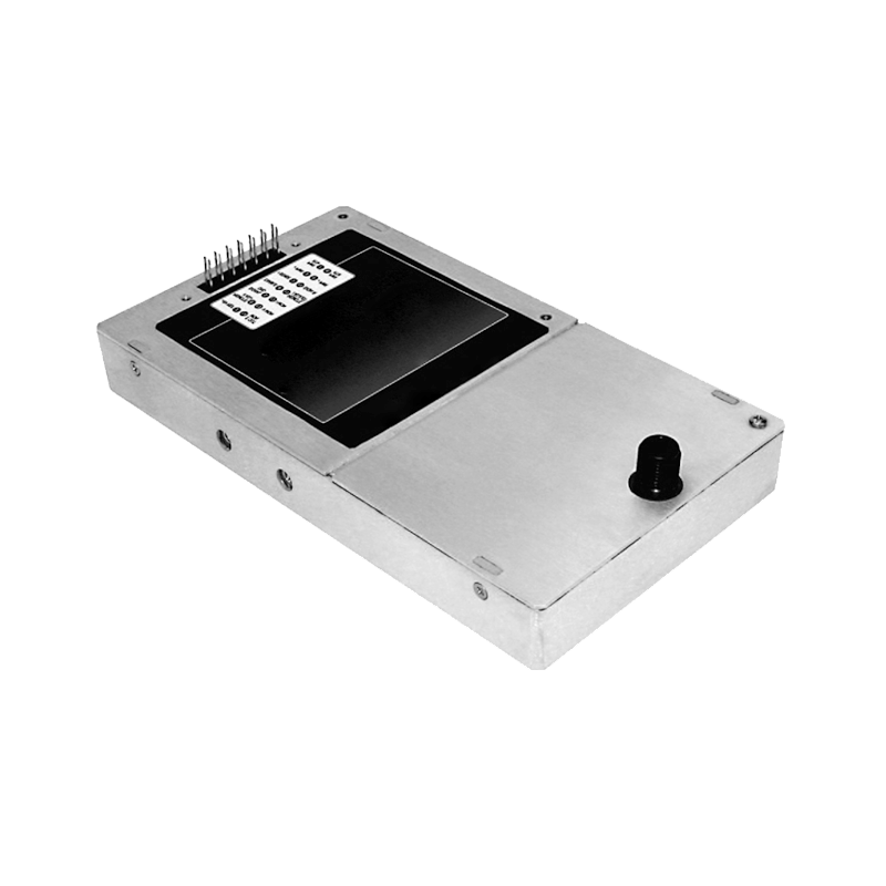
The backscattered electron detector typically operates as a solid-state diode or a scintillator-photomultiplier combination. In solid-state detectors, semiconductor junctions collect the backscattered electrons and generate a current proportional to the electron flux. The detector bias voltage, typically several tens to hundreds of volts, creates the electric field that collects the electrons. Any noise on this bias voltage modulates the collection efficiency and introduces noise into the detected signal.
The noise requirements for detector bias supplies are extremely stringent. The signal levels from backscattered electron detectors are often in the nanoampere range or below. The bias voltage noise must be low enough that the resulting signal modulation is negligible compared to the inherent signal fluctuations. For high-resolution imaging, the noise specification may be in the microvolt range or below, representing stability measured in parts per million.
Sources of noise in high voltage power supplies include several mechanisms. Thermal noise arises from the random motion of charge carriers in resistive components. Shot noise results from the discrete nature of charge carriers in semiconductor junctions. Switching noise originates from the power conversion circuits in switching power supplies. Ripple from the rectification process appears as periodic fluctuations at the power line frequency or switching frequency. Each noise source contributes to the overall noise performance.
Linear power supplies offer advantages for low-noise applications compared to switching supplies. The absence of high-frequency switching eliminates the associated switching noise. The output regulation uses linear pass elements that provide smooth, continuous control of the output voltage. However, linear supplies have lower efficiency and generate more heat than switching supplies, requiring careful thermal management.
For applications requiring the efficiency of switching supplies, careful design can achieve low noise performance. High switching frequencies allow smaller filter components and push the switching noise to frequencies where filtering is more effective. Synchronous rectification reduces the noise associated with diode recovery. Spread-spectrum techniques distribute the switching noise over a wider frequency range, reducing the noise density at any particular frequency. Post-regulation with linear stages can further reduce the output noise.
Filtering is essential for achieving the required noise performance. Low-pass filters attenuate high-frequency noise components. Pi-filters and T-filters provide multiple stages of filtering with appropriate impedance matching. The filter components must be selected for low noise characteristics, with low equivalent series resistance capacitors and low noise resistors. The filter design must balance noise attenuation with response speed for applications requiring voltage adjustment.
Grounding and shielding practices significantly affect the noise performance. The detector bias supply must be properly grounded to avoid ground loops that could introduce noise. Shielding enclosures prevent electromagnetic interference from coupling into the sensitive detector circuits. Cable routing must separate the bias supply connections from noise sources such as motor drives and switching electronics. The entire signal path from power supply to detector must be designed for minimal noise pickup.
Temperature stability affects the noise performance through temperature-dependent component characteristics. Temperature coefficients of reference voltages and feedback resistors cause the output voltage to drift with temperature changes. This drift can appear as low-frequency noise if the temperature fluctuates. Thermal design that maintains stable temperatures minimizes this contribution. Temperature compensation circuits can further reduce the temperature sensitivity.
Measurement of noise performance requires specialized techniques. Spectrum analyzers characterize the noise in the frequency domain, identifying the noise sources and their contributions. Time-domain measurements with high-resolution voltmeters capture the peak-to-peak noise fluctuations. Correlation with imaging results demonstrates the impact of power supply noise on image quality. These measurements guide the optimization of the power supply design for detector applications.