Pressure-resistant and Watertight Design of High Voltage Power Supply for Underwater Unmanned Vehicle Acoustic Payload
Underwater unmanned vehicles have become essential tools for ocean exploration, surveillance, and various commercial applications. These vehicles carry acoustic payloads for sonar imaging, communication, and environmental sensing. The high voltage power supplies that power the acoustic transducers must operate reliably in the underwater environment, where the hydrostatic pressure can reach hundreds of atmospheres and water ingress can cause catastrophic failure. The pressure-resistant and watertight design of these power supplies is critical for mission success.
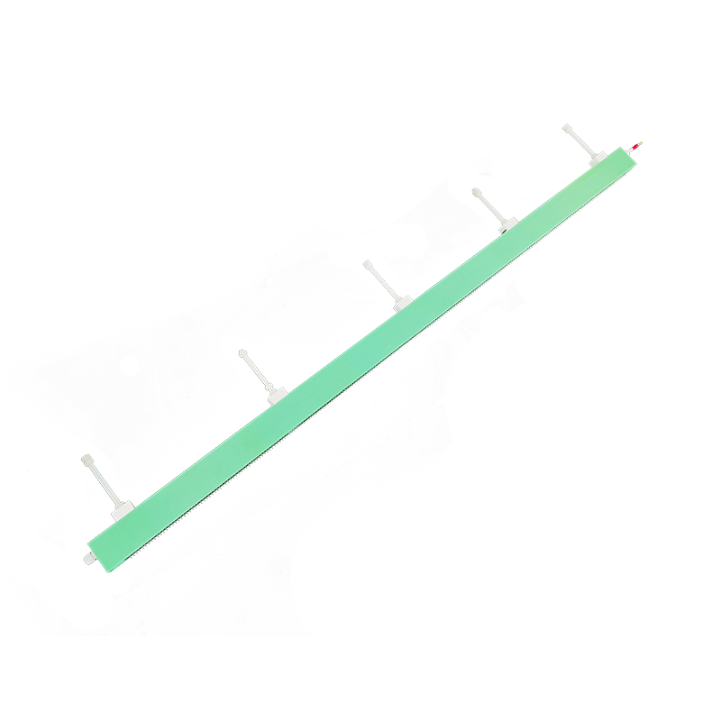
The acoustic payload typically includes transducers that convert electrical energy into acoustic energy for transmission, and convert received acoustic energy back into electrical signals. The transducers may operate at high voltages, ranging from hundreds to thousands of volts, to generate the required acoustic power. The power supply must deliver this high voltage while operating in the underwater environment.
The hydrostatic pressure in the ocean increases by approximately one atmosphere for every ten meters of depth. Vehicles operating at depths of several kilometers experience pressures exceeding several hundred atmospheres. This pressure can crush conventional pressure housings or force water past seals into the equipment. The power supply design must address this extreme pressure environment.
Pressure-resistant design uses strong housings to resist the external pressure without collapse. Cylindrical and spherical housings provide the most efficient pressure-resistant shapes, with the stress distributed uniformly around the circumference. The wall thickness must be sufficient to withstand the pressure with an appropriate safety factor. The material selection must consider strength, corrosion resistance, and compatibility with the internal components.
Watertight design prevents water from entering the housing through seals and connectors. O-rings provide the primary sealing mechanism for removable covers and connectors. The O-ring material must be compatible with the operating temperature range and the seawater environment. The O-ring groove design must ensure proper compression and sealing under all operating conditions. Multiple seals in series provide redundancy against seal failure.
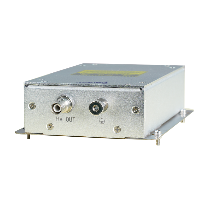
Connector design is critical for watertight integrity. The connectors must maintain sealing while providing electrical connections to the external transducers and control systems. Underwater connectors use rubber molding or glass-to-metal seals to provide waterproof electrical feedthroughs. The connector design must accommodate the pressure differential and the thermal expansion and contraction during operation.
Pressure-compensated design offers an alternative approach that eliminates the need for heavy pressure-resistant housings. In this approach, the housing is filled with a dielectric fluid that transmits the external pressure throughout the internal volume. The housing only needs to contain the fluid and prevent water ingress, without resisting the full hydrostatic pressure. The fluid must have suitable dielectric properties for the high voltage components and must remain stable under pressure.
The dielectric fluid selection for pressure-compensated systems requires careful consideration. The fluid must have high dielectric strength to insulate the high voltage components. The fluid must have low viscosity to flow freely and equalize pressure throughout the system. The fluid must be compatible with all materials in the power supply, including insulation, conductors, and electronic components. The fluid must not absorb water or gases that could affect its properties.
Component selection for underwater power supplies must consider the operating environment. Components that generate heat may require thermal paths to the housing for heat dissipation to the surrounding water. Components that are sensitive to pressure may require protection or pressure compensation. The component arrangement must facilitate potting or fluid filling if these techniques are used.
Potting encases the electronic components in a solid or gel material that provides mechanical support, thermal conduction, and environmental protection. The potting material must have suitable dielectric properties and must adhere well to the components and housing. The potting process must eliminate voids that could cause electrical stress concentration or could collapse under pressure. The potting material thermal expansion must be compatible with the components to avoid stress during temperature changes.
Testing validates the pressure-resistant and watertight design before deployment. Pressure testing in hyperbaric chambers subjects the power supply to the expected operating pressure and beyond to verify the pressure resistance. Leak testing verifies the watertight integrity under pressure. Thermal testing verifies operation over the expected temperature range. Vibration and shock testing verify survival of the handling and deployment environments.
Maintenance and repair considerations affect the design choices. Pressure-compensated systems require maintenance of the fluid level and quality. Potting makes component replacement difficult or impossible. Modular designs can enable replacement of failed modules rather than repair of individual components. The maintenance procedures must be designed to restore the pressure-resistant and watertight integrity after any maintenance action.