Beam Forming and Focusing Precision Control of High Voltage Transmitter Power Supply for Ultrasound Imaging
Ultrasound imaging has revolutionized medical diagnostics by providing real time, noninvasive visualization of internal structures. The image quality depends critically on the beam forming and focusing capabilities of the transducer array. The high voltage transmitter power supply that drives the transducer elements must provide precise, controllable pulses to achieve the required beam characteristics. Control of beam forming and focusing precision is essential for high resolution imaging.
Ultrasound transducers use arrays of piezoelectric elements that convert electrical pulses into acoustic waves. By exciting the elements with appropriately timed pulses, the acoustic waves combine to form a focused beam. The timing of the pulses to each element determines the beam direction and focal point. Precise control of the pulse timing enables electronic scanning and focusing without mechanical movement of the transducer.
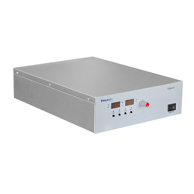
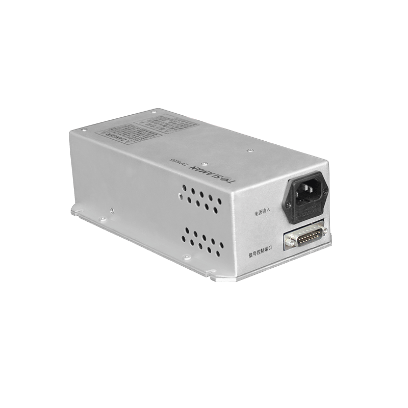
The high voltage power supply provides the electrical energy for the transmit pulses. Typical medical ultrasound transmitters operate at voltages from tens to hundreds of volts, with pulse durations of a few cycles at the transducer center frequency. The supply must deliver these pulses with precise timing and amplitude control for each element in the array.
Beam forming combines the signals from multiple transducer elements to create a directional beam. The beam direction is determined by the relative timing of the pulses to each element. Delays are applied to the element excitations so that the acoustic waves from all elements arrive in phase at the desired beam direction. The delay values depend on the element positions and the steering angle.
Dynamic focusing adjusts the focal depth during the transmit pulse. The focal point is where the acoustic waves from all elements converge. By applying delays that vary during the pulse, the focal point can be swept through the depth range. This dynamic focusing maintains a tight focus throughout the imaging depth, improving lateral resolution.
Aperture control adjusts the number of active elements during the transmit. A larger aperture provides better lateral resolution but has a narrower depth of field. A smaller aperture has a wider depth of field but poorer resolution. Variable aperture during the pulse can optimize the resolution at each depth.
The transmit voltage determines the acoustic pressure amplitude and thus the signal strength. Higher voltages produce stronger signals that can penetrate deeper or image more attenuating tissues. However, higher voltages also increase the risk of bioeffects such as heating or mechanical effects. The voltage must be controlled to achieve the required signal strength within safety limits.
Pulse shaping controls the frequency content and the temporal characteristics of the transmit pulse. The pulse typically consists of several cycles at the transducer center frequency. The envelope shape affects the bandwidth and the axial resolution. Gaussian or other smooth envelopes provide good bandwidth with minimal ringing. Rectangular envelopes have broader bandwidth but more sidelobes.
Coded excitation uses phase or frequency modulated pulses to increase the penetration depth without increasing the peak pressure. The coded pulse has lower peak amplitude but similar total energy to a conventional pulse. Pulse compression on receive recovers the axial resolution. This technique requires precise control of the transmit waveform.
The power supply must provide multiple independent channels for the transducer elements. Each channel must have independently controllable timing and amplitude. The number of channels depends on the transducer array size, which can be sixty-four to several hundred elements. The channel timing resolution determines the achievable beam steering precision.
Timing jitter in the pulse generation degrades the beam quality. Jitter causes the actual pulse timing to vary from the commanded timing. This variation causes phase errors in the beam forming, reducing the main lobe amplitude and increasing sidelobe levels. The timing jitter must be a small fraction of the acoustic period for good beam quality.
Amplitude variations between channels cause amplitude apodization errors. The intended apodization profile weights the element excitations to control the beam shape. Variations in the actual amplitudes from the commanded values distort the apodization, affecting the beam pattern. The amplitude accuracy must be sufficient to maintain the desired beam characteristics.
Calibration of the transmit system characterizes the actual timing and amplitude of each channel. Measurements using hydrophones or other acoustic sensors determine the actual acoustic output. The calibration data can be used to correct the drive signals to achieve the intended beam characteristics. Regular calibration maintains the imaging quality over the life of the system.