Response Time Optimization of High Voltage Fast Switching Power Supply for Superconducting Magnet Protection
Superconducting magnets require protection systems to prevent damage in the event of a quench, where a portion of the magnet transitions from superconducting to normal state. The protection system must detect the quench and take action quickly to prevent excessive heating and potential magnet damage. The high voltage fast switching power supply is a critical component of the protection system, and its response time directly affects the protection effectiveness.
Superconducting magnets operate at cryogenic temperatures where the conductor has zero electrical resistance. The magnet carries large currents, often hundreds or thousands of amperes, to generate strong magnetic fields. The stored energy in the magnet can be tens to hundreds of megajoules. If a quench occurs, the normal zone has resistance and dissipates energy as heat.
The quench begins at a localized point and propagates along the conductor. The propagation velocity depends on the conductor design, the cooling, and the operating current. The normal zone grows, and the resistance increases. The current begins to decrease as the resistance dissipates the stored energy. The heating in the normal zone must be limited to prevent damage to the conductor or insulation.
Quench detection identifies the onset of a quench by monitoring voltage across sections of the magnet. In the superconducting state, there is no voltage drop across the conductor. When a quench occurs, resistance appears and a voltage develops across the normal zone. The detection system must distinguish this quench voltage from inductive voltages during normal operation.
Once a quench is detected, the protection system takes action to limit the consequences. The protection may include firing heaters to spread the quench over a larger volume, activating energy extraction to remove the stored energy from the magnet, or activating a dump switch to discharge the magnet into a dump resistor.
The dump switch disconnects the power supply and connects the magnet to a dump resistor. The resistor dissipates the stored energy, reducing the current and the heating in the magnet. The switch must operate quickly to minimize the delay before energy extraction begins. The response time of the switch directly affects the peak temperature in the quench zone.
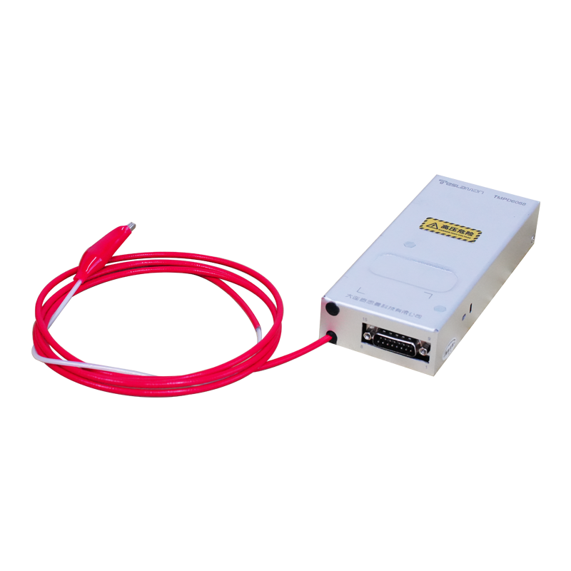
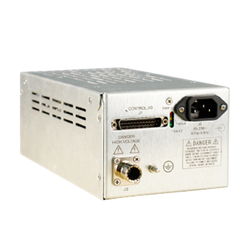
The high voltage power supply for the dump switch must charge a capacitor or provide the energy to operate the switch mechanism. The switch may be a thyristor, an ignitron, or a mechanical switch with appropriate triggering. The power supply must provide the trigger energy with minimal delay after receiving the quench detection signal.
Response time optimization minimizes the total delay from quench detection to energy extraction. The delay includes the detection time, the signal propagation time, the power supply response time, and the switch operation time. Each component must be optimized to minimize the total.
The power supply response time depends on the output characteristics and the control loop. The supply must be able to deliver the trigger energy quickly when commanded. The output capacitance and the available current determine how quickly the required voltage or current can be established. The control loop must respond quickly to the trigger command.
Pre charging the trigger circuit reduces the response time. If the trigger energy is stored in a capacitor that is continuously charged, the trigger can be initiated immediately upon receiving the command. The capacitor must be maintained at the required voltage, with the power supply providing a trickle charge to compensate for leakage.
Redundancy in the protection system improves reliability. Multiple detection circuits and multiple switches can be provided, so that a single component failure does not disable the protection. The power supply may need to serve multiple switches or may have redundant supplies. The redundancy architecture must ensure that all components can respond when needed.
Testing of the protection system verifies the response time under realistic conditions. The test should simulate a quench and measure the timing of each step. The total response time must meet the requirements for magnet protection. Regular testing confirms that the system continues to meet requirements over the magnet operating life.