Synchronous Triggering Mechanism of High Voltage Strobe Light Power Supply for High Speed Ampoule Visual Inspection Line
High speed visual inspection of pharmaceutical ampoules demands precise synchronization between the illumination source and the image acquisition system to capture clear images of rapidly moving objects. Strobe light illumination powered by high voltage supplies provides the intense, brief flashes of light necessary to effectively freeze motion and reveal surface defects, particulate contamination, or fill level irregularities. The synchronous triggering mechanism that coordinates the strobe flash with camera exposure constitutes a critical determinant of inspection reliability and throughput in pharmaceutical manufacturing quality control operations.
The fundamental challenge in high speed visual inspection arises from the continuous motion of ampoules along the production line, typically traveling at speeds of several meters per second. Conventional continuous illumination would result in motion blur during the camera exposure, obscuring the fine details necessary for reliable defect detection. Strobe illumination addresses this limitation by producing extremely brief light pulses with durations measured in microseconds, effectively freezing the motion of the ampoule during the exposure period. The high peak intensity achievable with strobe illumination compensates for the brief duration, providing sufficient total light energy to produce well exposed images despite the short exposure time.
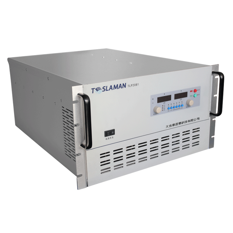
The high voltage power supply for strobe light operation typically utilizes xenon flash lamps as the light emitting element. These lamps contain xenon gas at reduced pressure and produce intense white light when an electrical discharge passes through the gas. The flash lamp requires a high voltage trigger pulse to ionize the xenon gas and initiate the discharge, followed by a main discharge from an energy storage capacitor that determines the flash intensity and duration. The triggering mechanism must precisely time this sequence to coincide with the arrival of an ampoule at the inspection position and the opening of the camera shutter.
Position sensors along the production line detect the approach of ampoules and generate timing signals that initiate the inspection sequence. Optical sensors, inductive proximity sensors, or mechanical triggers may be employed depending on the ampoule material, size, and line configuration. The sensor signal triggers a sequence of timed events including camera exposure initiation, strobe flash triggering, and image transfer to the processing system. The precise delay between the sensor trigger and strobe flash must account for the transit time of the ampoule from the sensor location to the inspection position, the response time of the triggering electronics, and any inherent delays in the camera shutter mechanism.
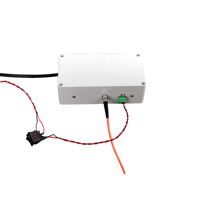
The triggering electronics typically incorporate programmable delay generators that allow fine adjustment of the timing relationships between the sensor signal, strobe trigger, and camera trigger. This adjustability enables optimization of the synchronization for different ampoule sizes, line speeds, and camera exposure settings. The delay resolution must be sufficient to position the strobe flash within the optimal portion of the camera exposure window, typically requiring microsecond level timing precision. Modern digital timing systems provide the necessary resolution and stability while offering convenient interfaces for parameter adjustment and monitoring.
Multiple inspection stations along a production line may require independent strobe triggering to examine different aspects of the ampoules or to inspect both front and back surfaces. Coordinating the triggering of multiple strobes with the appropriate camera exposures adds complexity to the timing system design. Cross talk between triggering channels must be minimized to prevent unintended flash activation that could degrade image quality or reduce lamp lifetime. The triggering system architecture must accommodate the required number of synchronized channels while maintaining the timing precision and reliability necessary for each inspection task.
The high voltage trigger pulse for the xenon flash lamp typically originates from a pulse transformer that steps up a lower voltage trigger signal to the several kilovolts required for reliable lamp ionization. The trigger electrode may be external to the flash lamp envelope, wrapped around the lamp in a conductive band, or internal as a wire or electrode structure within the lamp itself. External trigger configurations simplify lamp replacement and reduce the voltage requirements on the trigger circuit but may require higher trigger voltages for reliable ionization. Internal trigger electrodes provide more reliable triggering at lower voltages but complicate lamp construction and replacement.
The main discharge circuit includes the energy storage capacitor, the flash lamp, and associated switching and current limiting components. The capacitor is charged to a voltage determined by the desired flash energy, with the stored energy being proportional to the capacitance and the square of the voltage. When the trigger pulse ionizes the lamp, the capacitor discharges through the lamp producing the intense light flash. The discharge duration depends on the capacitance value, the lamp impedance characteristics, and any series inductance or resistance in the discharge path. Shorter flash durations require smaller capacitance values and higher discharge currents, placing greater demands on the lamp and circuit components.
Flash repetition rate capabilities depend on the charging system capacity and the thermal management of the flash lamp. The charging system must restore the capacitor voltage between flashes, with the required charging power being proportional to the flash energy and repetition frequency. High speed inspection lines may require flash rates of hundreds or even thousands per second, demanding substantial charging power and efficient thermal dissipation from the flash lamp. The lamp envelope, electrodes, and surrounding cooling structures must dissipate the average power input without excessive temperature rise that would degrade lamp lifetime or shift the spectral characteristics of the emitted light.
The synchronization system must accommodate variations in ampoule spacing and line speed that may occur during production operation. Variable spacing between ampoules requires the triggering system to respond to each ampoule individually rather than relying on fixed timing intervals. Speed variations affect the transit time from the position sensor to the inspection point, potentially requiring adaptive delay adjustment to maintain optimal synchronization. Advanced triggering systems may incorporate speed measurement from encoder signals or differential timing between multiple sensors to dynamically adjust the strobe trigger delay for changing line conditions.
Jitter in the triggering timing degrades the effective resolution of the inspection system by introducing uncertainty in the relationship between the image capture instant and the ampoule position. Sources of timing jitter include sensor response variations, electronic noise in the triggering circuits, and statistical variations in the flash lamp ionization delay. Minimizing jitter requires careful attention to signal integrity, component selection, and circuit layout in the triggering electronics. Differential signaling techniques, proper grounding practices, and shielding of sensitive circuits help reduce noise induced jitter in the timing signals.
The spectral characteristics of the strobe illumination influence the image quality and defect detection capabilities of the inspection system. Xenon flash lamps emit a broad spectrum approximating daylight, which provides good color rendering for visual inspection but may include ultraviolet components that could affect light sensitive pharmaceutical products. Filtering elements may be incorporated to remove ultraviolet or infrared components as appropriate for the inspection requirements and product sensitivity. The spectral output may also vary with lamp age, operating conditions, and the specific lamp construction, necessitating periodic verification or compensation in the image processing algorithms.