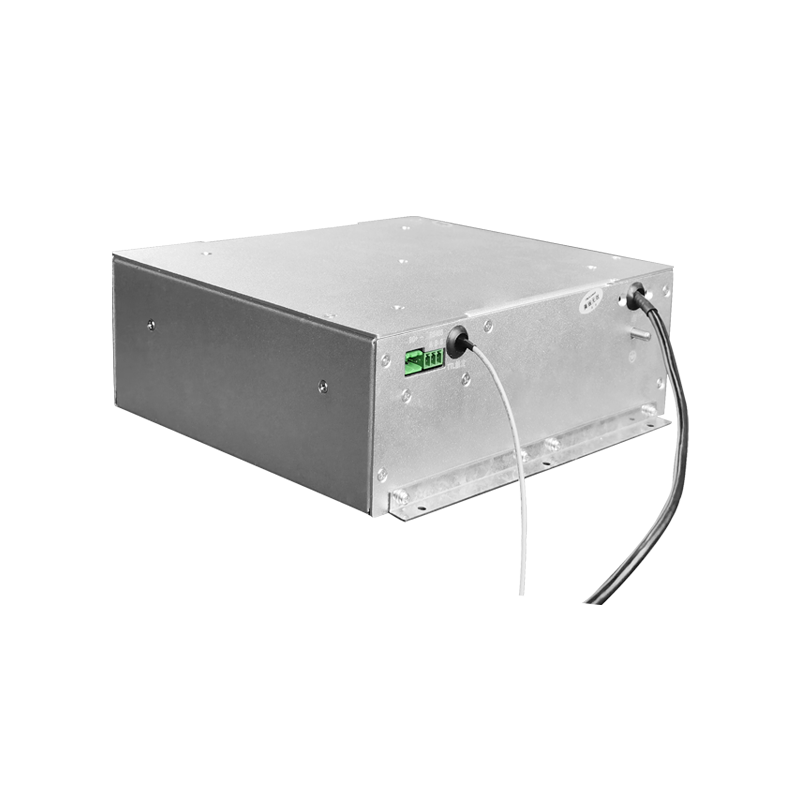
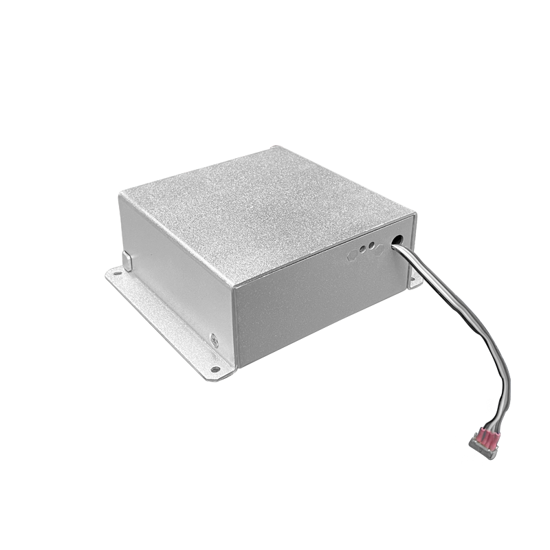
Flexible Use of Positive-Negative Switching High-Voltage Supply in Laboratory Electrostatic Multi-Function Test Platform
A positive-negative switching high-voltage supply serves a multi-function electrostatic test platform where different experiments require both polarities and a wide range of voltages. The flexibility of the platform depends on the range, the switching behavior, and the protection functions of the supply, and the supply design must accommodate the diverse load conditions.
The output range covers the voltages needed by the various test setups, and the range is divided into programmable steps. The step resolution is set by the smallest voltage change required by the most sensitive setup, and the resolution is verified with a calibrated voltmeter.
The polarity reversal is controlled by the switching sequence. The sequence discharges the load capacitance, verifies the discharge, and rebuilds the voltage in the opposite polarity. The reversal time is programmable, and the fast mode is used where the setup tolerates the higher switching stress.
The load connected to the platform varies with the experiment. Some setups present a high-impedance load with a negligible current, and others draw a substantial current from the output. The supply must remain stable across the load range, and the stability is verified at the load extremes.
Protection functions are configured for each test setup. The overcurrent limit, the overvoltage limit, and the arc detection sensitivity are programmable, and the settings are stored with the test recipe. A protective trip is recorded with the output trajectory for the analysis.
The grounding of the test platform is a critical part of the measurement quality. The supply chassis, the test bench, and the measuring instruments share a star ground, and the ground impedance is measured at the installation. A ground loop degrades the measurement and the supply stability.
The user interface provides the voltage setting, the polarity selection, and the ramp control. The settings are validated by the firmware, and an invalid combination is rejected with a clear message. The interface records the operating history for the traceability of the test results.
The calibration of the supply follows the test platform schedule. The voltage accuracy, the ripple, and the reversal timing are verified against traceable standards, and the results are documented. The documentation supports the quality system of the laboratory.
Operator handover between shifts includes the equipment status, the pending issues, and the instructions for the current operation. The handover log is signed by both parties, and the entries are concise and factual. The handover discipline maintains the continuity of the operation.
Performance monitoring covers the key parameters that indicate the health of the supply. The monitoring points and the thresholds are defined during commissioning, and the measured values are recorded on a regular basis. The monitoring data support the early detection of the degradation trends.
Long-term stability of the supply is verified by the periodic re-measurement of the output characteristics. The measurements are compared with the baseline recorded at acceptance, and the drift trend is analyzed. A drift beyond the tolerance triggers a detailed investigation and a corrective action.
Troubleshooting flow guides the maintenance crew from the symptom to the probable cause. The flow is built from the documented fault cases and the component knowledge. The use of the flow shortens the diagnosis time and reduces the trial-and-error work.
System integration between the supply and the process controller is validated with the interface tests. The signal definitions, the timing, and the fault propagation are verified under the representative conditions. The integration records are kept with the system documentation.
Upgrade planning assesses the compatibility, the benefit, and the risk of each proposed change. The upgrade is implemented in stages with a verification at each stage. The upgrade records are updated in the configuration documentation.
Cost analysis of the equipment includes the purchase price, the installation, the energy, the maintenance, and the downtime. The cost data are collected over the service life and reviewed annually. The analysis outcome supports the replacement and the repair decisions.
Documentation of modifications records every change to the equipment, regardless of the size. The modification log includes the date, the reason, the implementer, and the verification result. The log is reviewed during the periodic audits to confirm that the documentation matches the hardware.
Measurement traceability connects the equipment readings to the national standards through a chain of calibrated instruments. Each link in the chain has a calibration record with the uncertainty statement. The traceability is audited at the planned intervals.
Interface management defines the boundary between the supply and the surrounding systems. The mechanical, electrical, and data interfaces are documented and controlled. A change on either side of an interface is coordinated through the change review process.
Configuration control ensures that the operating configuration of the supply is known and reproducible. The firmware version, the parameter set, and the hardware revision are recorded together. The configuration record is used to reproduce a known-good state after a fault.
Field experience feedback collects the observations from the operating sites and feeds the observations into the design and the maintenance practice. The feedback items are categorized and reviewed at the defined intervals. The implemented feedback is documented in the equipment history.
Periodic review of the equipment covers the performance, the maintenance, and the cost since the last review. The review findings are summarized into the recommendations for the next period. The review is scheduled annually or when a significant event occurs.
Commissioning of the supply starts with a visual inspection of the high-voltage section and the cooling path, followed by a no-load voltage check and a load test at the rated output. The acceptance data are recorded against the specification table, and any deviation is resolved before the equipment enters service. The commissioning report becomes the baseline for all later comparisons.
Acceptance testing covers the electrical performance, the protective functions, and the mechanical integrity. The test sequence is defined in the procurement document, and each test has a pass criterion. The signed acceptance record accompanies the equipment through the service life and supports the warranty claims when a defect appears.
Preventive maintenance scheduling follows the operating hours recorded by the supply itself. The maintenance tasks are grouped by interval, and the short-interval tasks are performed during the regular downtime windows. The long-interval tasks are planned into the annual shutdown. The maintenance history is kept with the equipment and reviewed when the interval policy is updated.