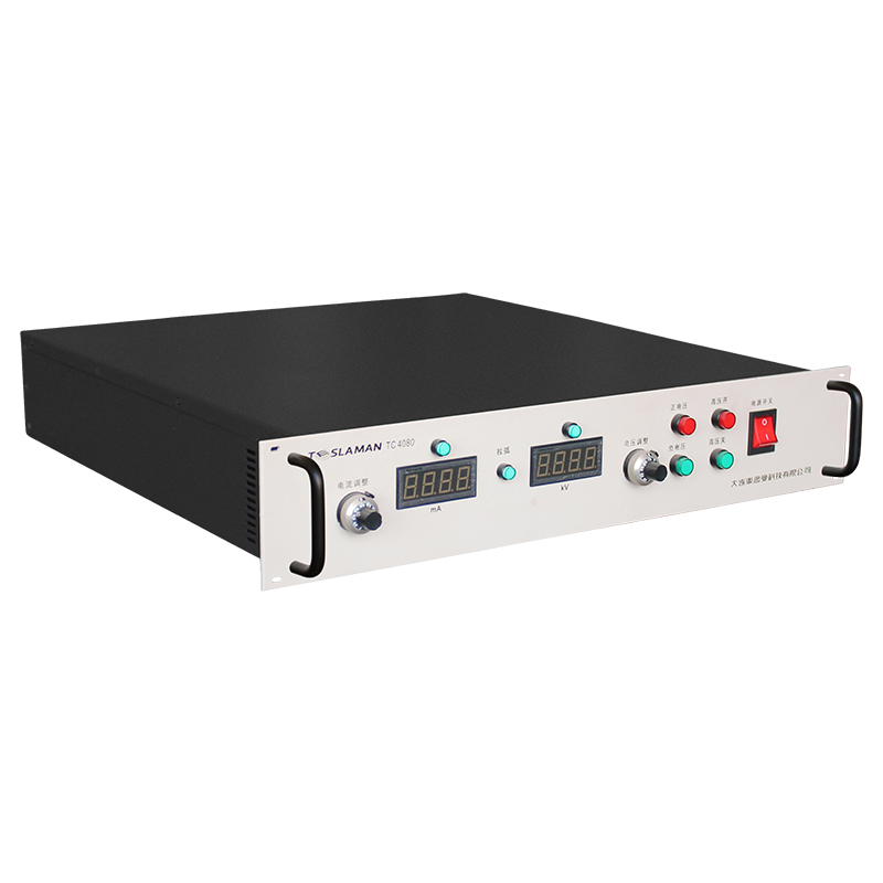
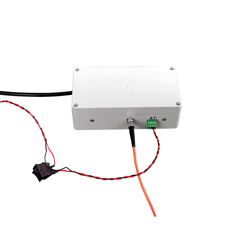
Magnetron Sputtering High-Voltage Power Supply Feedback in Large Vacuum Equipment and Optical Film Deposition
Magnetron sputtering systems deposit optical films in large vacuum chambers, and the high-voltage supply that feeds the target determines the deposition rate and the film uniformity. Feedback control of the discharge keeps the process stable while the target condition changes, and the design of that control loop is the deciding factor for coating quality on large substrates.
Discharge stability depends on the regulation of the target voltage and current. The supply operates in constant power, constant voltage or constant current mode depending on the process phase, and the mode is selected to keep the discharge confined and the deposition rate stable. Mode transitions are controlled to avoid transients that disturb the film.
Optical films require tight thickness uniformity across large substrates. The deposition rate must hold constant across the full target area, which depends on the magnetic field configuration and the stability of the power delivered to the target. A supply that wavers in power produces thickness gradients that shift the optical performance of the coating.
Target condition changes continuously during the run. Erosion of the target surface changes the discharge impedance, and the supply compensates by adjusting the operating point. The compensation range is limited, and when the target is consumed the discharge becomes unstable; the supply detects the instability and signals that the target needs replacement.
Arc events are frequent in reactive sputtering. The arc suppression circuit detects the current spike, extinguishes the arc quickly, and resumes the discharge after a short recovery. The recovery time must be short enough that the film deposition is not interrupted, and the arc rate is logged as a process indicator.
Ripple on the target power couples into the plasma and modulates the deposition. The filter network is designed so that the residual ripple stays below the level where ripple affects the film structure, and the filter performance is verified during maintenance. Capacitor aging is monitored because aging degrades the ripple suppression over time.
Feedback response is tuned against the chamber impedance. The plasma impedance varies with pressure and gas flow, and the control loop must remain stable across the whole range. The loop gain and phase margin are verified at the operating points used by the production recipes, and the tuning is documented for each process.
Thermal management of the supply matches the continuous duty of the coater. The power stage losses heat the cabinet, and the cooling system holds the component temperatures within the derating envelope across a full shift. Temperature data is logged and trended, and the maintenance schedule reacts to the thermal history rather than a fixed calendar.
Reliability assessment uses the field data collected from the equipment population. The failure rate, the repair time, and the availability are computed over a rolling period, and the results are compared with the design targets. The assessment output feeds the capital replacement plan and the spares strategy.
Energy efficiency of the supply affects the operating cost and the cooling load. The efficiency is measured at the representative operating points, and the improvement opportunities are evaluated against the implementation cost. The efficiency records are maintained for the lifetime comparison.
Training programs for the operating and maintenance staff are scheduled at defined intervals. The training covers the safe operation, the routine checks, and the fault diagnosis flow. The training effectiveness is verified with a written test and a practical exercise, and the results are filed with the personnel records.
Process qualification is performed whenever the equipment or the process recipe changes. The qualification plan defines the test articles, the acceptance criteria, and the data to be recorded. The qualification report is approved before the new condition enters production.
Failure analysis follows a defined path from the symptom to the root cause. The analysis uses the logged data, the physical evidence, and the repair records. The analysis conclusion is documented with the corrective action, and the corrective action is verified after implementation.
Quality records link the equipment performance to the product quality. The operating parameters and the product measurements are filed together, so that a product deviation can be traced to the equipment condition. The record retention period follows the regulatory and contractual requirements.
Vendor coordination covers the technical support, the spare supply, and the repair service. The service level agreement defines the response time and the repair turnaround. The vendor performance is reviewed periodically, and the review outcome influences the future procurement decisions.
Continuous improvement is driven by the analysis of the failure data and the operating experience. Each improvement proposal is assessed for the benefit, the cost, and the risk before implementation. The implemented improvements are tracked for the realized benefit.
Operator handover between shifts includes the equipment status, the pending issues, and the instructions for the current operation. The handover log is signed by both parties, and the entries are concise and factual. The handover discipline maintains the continuity of the operation.
Performance monitoring covers the key parameters that indicate the health of the supply. The monitoring points and the thresholds are defined during commissioning, and the measured values are recorded on a regular basis. The monitoring data support the early detection of the degradation trends.
Long-term stability of the supply is verified by the periodic re-measurement of the output characteristics. The measurements are compared with the baseline recorded at acceptance, and the drift trend is analyzed. A drift beyond the tolerance triggers a detailed investigation and a corrective action.
Troubleshooting flow guides the maintenance crew from the symptom to the probable cause. The flow is built from the documented fault cases and the component knowledge. The use of the flow shortens the diagnosis time and reduces the trial-and-error work.
System integration between the supply and the process controller is validated with the interface tests. The signal definitions, the timing, and the fault propagation are verified under the representative conditions. The integration records are kept with the system documentation.
Upgrade planning assesses the compatibility, the benefit, and the risk of each proposed change. The upgrade is implemented in stages with a verification at each stage. The upgrade records are updated in the configuration documentation.
Cost analysis of the equipment includes the purchase price, the installation, the energy, the maintenance, and the downtime. The cost data are collected over the service life and reviewed annually. The analysis outcome supports the replacement and the repair decisions.