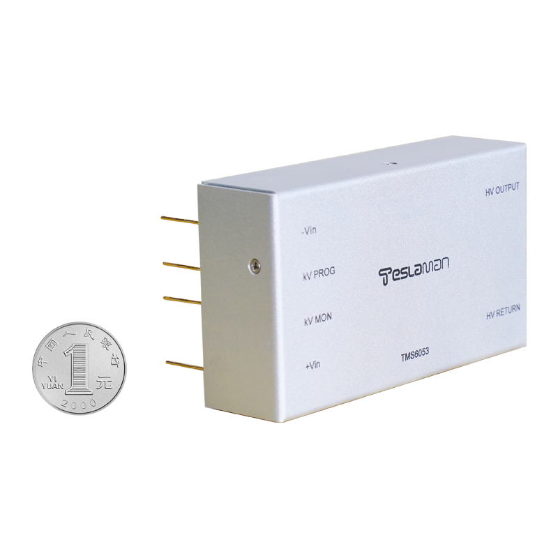
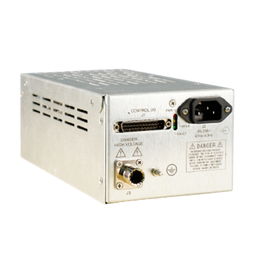
Mass Spectrometer High-Voltage Power Supply Low-Ripple Requirements in Environmental Pollutants and Trace Analysis
Mass spectrometers used for environmental monitoring and trace analysis operate at the limit of detection, and the high-voltage supply that feeds the ion optics and the detector has a direct influence on the noise floor. Low-ripple requirements dominate the design because any modulation of the lens voltages or the detector bias appears as signal fluctuation.
Ion transmission through the optics is sensitive to the lens voltage accuracy. A stable lens voltage keeps the ion beam focused and centered, while ripple on the lens supply broadens the beam and reduces the signal. The supply holds the lens voltages within a tight tolerance, and the regulation loop is verified against the mass calibration of the instrument.
Detector bias stability sets the gain of the electron multiplier. The gain depends exponentially on the applied voltage, so a small voltage drift produces a measurable gain change. The bias supply therefore uses a high-stability reference and temperature compensation, and the drift specification is tight enough that the gain remains within the calibration band between service intervals.
Ripple on the detector bias modulates the gain at the ripple frequency, which appears as a sideband on every mass peak. The filter network is designed to attenuate the switching ripple to a level far below the signal noise, and the filter performance is verified during commissioning with a spectrum analyzer on the detector output.
Transient behavior is exercised when the instrument switches between scan modes. The lens voltages change stepwise between methods, and the supply must settle without overshoot so that the mass axis does not shift during the transition. The settling time is characterized and recorded, and the method sequence is arranged to avoid measurements during the transition.
Grounding and shielding are as important as the supply itself. The high-voltage section is grounded at a single point, the cables are shielded and terminated correctly, and the shield currents are kept away from the signal path. A grounding review during installation prevents ground loops that would otherwise couple supply noise into the analyzer.
Long-term drift of the lens and detector supplies is corrected by the instrument calibration routine. The mass calibration runs periodically and adjusts the mass axis, and the correction values are logged. A steadily growing correction signals supply drift, and the maintenance schedule responds before the drift exceeds the calibration range.
Environmental factors in the laboratory affect the supply stability. Temperature changes shift the reference and the divider resistors, so the instrument room temperature is controlled and the supply includes compensation for residual drift. The combination of controlled environment, compensation and periodic calibration keeps the instrument at the specified detection limit.
Training programs for the operating and maintenance staff are scheduled at defined intervals. The training covers the safe operation, the routine checks, and the fault diagnosis flow. The training effectiveness is verified with a written test and a practical exercise, and the results are filed with the personnel records.
Process qualification is performed whenever the equipment or the process recipe changes. The qualification plan defines the test articles, the acceptance criteria, and the data to be recorded. The qualification report is approved before the new condition enters production.
Failure analysis follows a defined path from the symptom to the root cause. The analysis uses the logged data, the physical evidence, and the repair records. The analysis conclusion is documented with the corrective action, and the corrective action is verified after implementation.
Quality records link the equipment performance to the product quality. The operating parameters and the product measurements are filed together, so that a product deviation can be traced to the equipment condition. The record retention period follows the regulatory and contractual requirements.
Vendor coordination covers the technical support, the spare supply, and the repair service. The service level agreement defines the response time and the repair turnaround. The vendor performance is reviewed periodically, and the review outcome influences the future procurement decisions.
Continuous improvement is driven by the analysis of the failure data and the operating experience. Each improvement proposal is assessed for the benefit, the cost, and the risk before implementation. The implemented improvements are tracked for the realized benefit.
Operator handover between shifts includes the equipment status, the pending issues, and the instructions for the current operation. The handover log is signed by both parties, and the entries are concise and factual. The handover discipline maintains the continuity of the operation.
Performance monitoring covers the key parameters that indicate the health of the supply. The monitoring points and the thresholds are defined during commissioning, and the measured values are recorded on a regular basis. The monitoring data support the early detection of the degradation trends.
Long-term stability of the supply is verified by the periodic re-measurement of the output characteristics. The measurements are compared with the baseline recorded at acceptance, and the drift trend is analyzed. A drift beyond the tolerance triggers a detailed investigation and a corrective action.
Troubleshooting flow guides the maintenance crew from the symptom to the probable cause. The flow is built from the documented fault cases and the component knowledge. The use of the flow shortens the diagnosis time and reduces the trial-and-error work.
System integration between the supply and the process controller is validated with the interface tests. The signal definitions, the timing, and the fault propagation are verified under the representative conditions. The integration records are kept with the system documentation.
Upgrade planning assesses the compatibility, the benefit, and the risk of each proposed change. The upgrade is implemented in stages with a verification at each stage. The upgrade records are updated in the configuration documentation.
Cost analysis of the equipment includes the purchase price, the installation, the energy, the maintenance, and the downtime. The cost data are collected over the service life and reviewed annually. The analysis outcome supports the replacement and the repair decisions.
Documentation of modifications records every change to the equipment, regardless of the size. The modification log includes the date, the reason, the implementer, and the verification result. The log is reviewed during the periodic audits to confirm that the documentation matches the hardware.
Measurement traceability connects the equipment readings to the national standards through a chain of calibrated instruments. Each link in the chain has a calibration record with the uncertainty statement. The traceability is audited at the planned intervals.