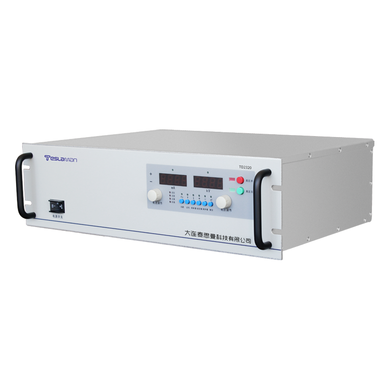
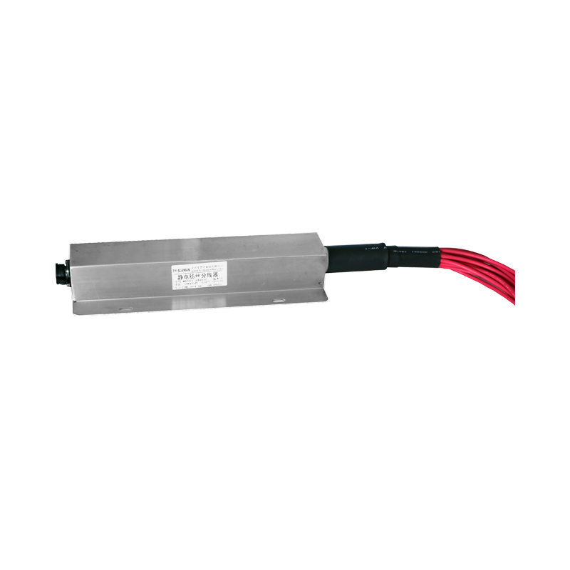
Multi-Channel Parallel Configuration of Electrospinning High-Voltage Power Supply in Nanomaterial and Composite Fiber Preparation
Multi-channel parallel configuration serves nanomaterial and composite fiber preparation where several spinnerets run at once. Each channel carries an independent voltage setting, and channel-to-channel deviation shifts the fiber diameter distribution, so per-channel regulation accuracy becomes the governing requirement.
The parallel channels share one input stage while the output stages remain separate. A single converter drives the shared bus, each channel converts to the local spinning voltage, and isolation between channels prevents cross-talk that would couple one spinneret instability into the neighboring jet.
Voltage regulation per channel uses a dedicated divider and a dedicated error amplifier. The reference for each channel is trimmed at commissioning, and the trim data is stored with the channel record, so replacement of one channel module keeps the original accuracy without disturbing the other channels.
Fiber diameter uniformity depends on the electric field at each spinneret. A constant voltage maintains the field, ripple on the output modulates the jet stretching, and the ripple specification is derived from the allowed diameter variation rather than from a generic percentage.
Environment changes affect the spinning process. Temperature alters the solution viscosity and conductivity, humidity changes the charge relaxation path, and the voltage set point must follow the ambient condition to keep the process window, which argues for environment-compensated settings.
The control loop bandwidth is chosen from the jet dynamics. Slow changes are handled by the regulating loop, fast disturbances by the storage capacitance at each channel, and a step test on the actual spinneret verifies the transient behavior under real load conditions.
Cross-talk between channels appears when the common input impedance is too high. The input bus carries a low-impedance storage bank, the bus inductance is minimized, and a load step on one channel produces no measurable disturbance on the neighboring output.
Grounding arrangement of the multi-channel unit follows a star topology. Each channel returns to the single reference point, the case is bonded at that point, and the spinning heads are grounded through the return path, which keeps the noise floor uniform across all channels.
Field commissioning records the voltage at every channel under identical process conditions. The readings are compared against the set points, deviation beyond the limit is corrected by trim adjustment, and the commissioning data becomes the baseline for later drift evaluation.
Long-running production reveals drift differences between channels. Some channels age faster because of uneven thermal loading, the periodic comparison against the baseline identifies the drifted channel, and corrective maintenance targets that channel instead of the whole unit.
Output cable capacitance differs with cable length per channel. Cable compensation is applied where the length differs significantly, the buffer network at the spinneret end is tuned, and the final waveform is checked at the head rather than at the cabinet terminal.
The unit log stores voltage, current and protection events with time stamps. The log supports drift analysis and fault tracing, the trend of each channel is reviewed periodically, and the review results feed the calibration schedule.
Insulation coordination starts with field distribution control. Electrode radii and shield placement determine the local field stress, and weak points show discharge precursors first. Field simulation verifies the stress margin at the design stage, and withstand testing confirms the result on the finished unit.
Filter network parameters balance ripple rejection against dynamic response. Larger output capacitance improves ripple but lengthens the voltage settling time, so the operating point is set from the actual load requirements rather than from a generic rule.
Thermal management decides power device lifetime. Losses concentrate in the switching devices and the magnetic components, and the heatsink thermal resistance plus the airflow path are sized for the worst-case duty. Temperature sensors are placed from the thermal analysis, and the data feeds the derating logic.
The reference and the divider network form the basis of voltage accuracy. The reference is selected for low drift, the divider resistors are matched, and the assembly is sealed against humidity. Calibration data is archived and periodic re-verification holds long-term precision.
Grounding practice controls the noise floor of control and measurement. Signal ground, power ground and chassis ground meet at a single point, ground loops are eliminated, and shield terminations follow a defined rule. Field commissioning verifies the grounding integrity before noise targets are assessed.
Protection timing matters as much as the protection itself. Hardware comparators cover microsecond fast response, software logic handles sustained faults, and the two layers cover different time scales. Action records support post-event analysis.
Electromagnetic compatibility is handled from the layout stage. Power lines, sampling lines and control lines run in separate routes, shields are terminated correctly, filter components sit close to the disturbance source, and conducted and radiated tests confirm the result.
Long-term drift monitoring adds more value than a single calibration. Output readback values are recorded as a time series, trend analysis reveals acceleration of drift, and predictive maintenance intervenes before failure, which reduces unplanned downtime.
Field commissioning starts with the supply conditions. Input voltage range, grounding resistance and grid harmonics determine the observed behavior of the supply, and control tuning cannot converge while supply-side problems remain unresolved.
Insulation material aging defines the maintenance interval. Dielectric strength, temperature rating and moisture resistance are selected for the working conditions of each part, aging test data supports the replacement plan, and insulation monitoring tracks the running state.
Soft-start control protects the power stage and the load. The voltage rises along a defined slope, the inrush current stays bounded, the establishment time matches the process cycle, and an abnormal start is aborted to a safe state.
Recovery speed under load steps is set by loop bandwidth and stored energy. Bandwidth is limited by sampling delay, feed-forward compensates the delay, storage capacitors provide transient energy, and step-response testing verifies the specification.
Current sampling accuracy serves both the control path and the protection path. The sampling resistor is low-drift and low-inductance, the signal is isolated in transmission, the gain is calibrated, and the sampling point sits close to the current path with parasitic parameters controlled.
The combination of switching frequency and filter network sets the ripple level. The resonant point sits below the switching frequency, capacitor equivalent series resistance and inductance are selected from high-frequency behavior, and spectrum analysis locates the residual ripple sources.
Fault diagnosis depends on complete running records. Voltage, current, temperature and protection events are stored with time stamps, fault signatures are compared with history, and corrective action updates the design and the maintenance strategy.