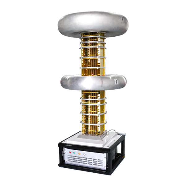
Precision Power Supply of Electron Beam System High-Voltage Power Supply in Vacuum Surface Treatment
Precision power supply of an electron beam system in vacuum surface treatment controls the beam energy and the dose at the treated surface. The accelerating voltage sets the penetration, the beam current sets the dose rate, and the precision of both defines the treatment uniformity.
The accelerating voltage is regulated against the beam load. The beam current changes with the cathode condition, the loop compensates the change, and the energy spread of the beam stays within the process tolerance.
The treatment dose is controlled by the beam current and the scan speed. The energy input per unit area is defined, the scan pattern is synchronized with the beam, and the surface temperature rise is limited by the power and the speed.
Ripple on the accelerating voltage widens the energy distribution. The filter network suppresses the ripple, the residual value is measured at the gun, and the treatment depth uniformity reflects the energy consistency.
Vacuum quality affects the beam behavior. The pressure is monitored, the high voltage is interlocked with the vacuum state, and the process runs within the allowed pressure window.
The beam blanking function controls the exposure. The blanking is fast and synchronized with the scan, the dose at the pattern edge is defined by the timing, and the surface treatment pattern is accurate.
Long-term operation drifts the cathode emission. The emission decay is compensated by the voltage or the current adjustment, the compensation is bounded, and the cathode service interval is derived from the trend.
Process verification uses the treated samples. The modified depth and the surface property are measured, the data is compared with the target, and the supply parameters are updated from the verification.
Fault handling on site follows the sequence of isolate first and investigate after. The first step after a fault is to remove the high voltage and confirm the discharge, then the input, the power stage, the sampling chain and the load are checked in order.
Electromagnetic compatibility problems are common in high-voltage equipment. The switching action of the power stage couples into the control circuit through the parasitic path, and the shielding and the grounding treatment decide the interference level, so the on-site diagnosis relies on the waveform record.
Grounding system handling is a key part of the high-voltage installation. The ground reference of the high-voltage side and the low-voltage side must be clear, the shield grounding choice between the single point and the multi point depends on the interference frequency, and the ground check belongs in the regular maintenance.
Component aging patterns form the basis of the maintenance schedule. The electrolytic capacitor capacitance decays with temperature and energizing time, the contact wear relates to the operation count, and the fan life depends on the running hours, so the maintenance plan follows the actual operating data.
Efficiency of a high-voltage supply differs clearly across the load points. The fixed loss share is high at light load, the conduction loss rises at full load, and the efficiency curve must be measured at several load points with the measurement condition stated in the documentation.
Control loop tuning must consider the dynamic character of the load. The response of a pure resistive load differs greatly from a capacitive load, the tuning is performed on the target load, the adjustment is verified by the step test, and the stability judgment relies on the phase margin and the waveform.
Sampling circuit accuracy decides the final control quality. The divider resistor temperature drift, the sampling point position and the signal path length all introduce error, the calibration covers the full range, and the calibration state is recorded and traceable.
Cleanliness of the high-voltage parts directly affects the insulation behavior. Dust and oil change the surface field distribution, especially at high humidity, the cleaning interval follows the field environment, and the insulation measurement data before and after the cleaning are compared.
Spare part management revolves around the failure modes. The high-failure-rate parts keep a moderate stock, the failure records feed back into the spare list, and the storage condition of the spares must meet the requirement because the long-stored capacitors need the reconditioning before the installation.
Verification after a modification cannot stop at the functional test. The affected performance items are re-measured one by one, the unaffected items are sampled for confirmation, the modification record is kept complete, and the drawing is updated to match the hardware.
Accumulated operating data form the foundation of the equipment health management. The voltage, the current and the temperature are recorded at a fixed interval, the abnormal events are archived separately, and the trend analysis becomes meaningful once enough data is collected.
Start-up of a high-voltage supply needs special attention. The start-up surge and the voltage build-up process stress the devices, the soft-start parameters are set from the load characteristic, the start-up waveform is verified, and the device state after repeated starts is included in the inspection.
Output filter design balances the ripple specification against the dynamic performance. Excessive filtering slows the response, insufficient filtering misses the specification, and the filter network design sits between the two, with the difference between the measured result and the calculation analyzed.
Protection class and the installation environment must match. Moisture, dust and corrosive gas accelerate the insulation degradation, the installation position and the enclosure class are selected for the actual environment, and the equipment adaptability is re-evaluated when the environment changes.
Drive circuit design of the switching devices focuses on the reliability. The drive voltage and the current satisfy the device requirement, the drive loop is short, the protection action is fast, and the drive related damage holds a notable share in the failure statistics.
High-voltage cable selection considers the electrical and the mechanical performance together. The voltage class keeps the margin, the shield structure matches the interference environment, the bending radius fits the installation space, and the cable state is included in the patrol.
Reliability of the control power forms the base of the whole equipment. Loss of the control power leaves the output state uncontrolled, the redundancy design follows the actual need, the monitoring covers the voltage and the state, and the handling logic is defined at the design stage.
Interference problems at the commissioning stage often relate to the layout. The spacing between the power line and the signal line, the grounding point choice and the shield treatment all affect the result, so the layout adjustment is re-verified and the interference solving relies on the systematic search.