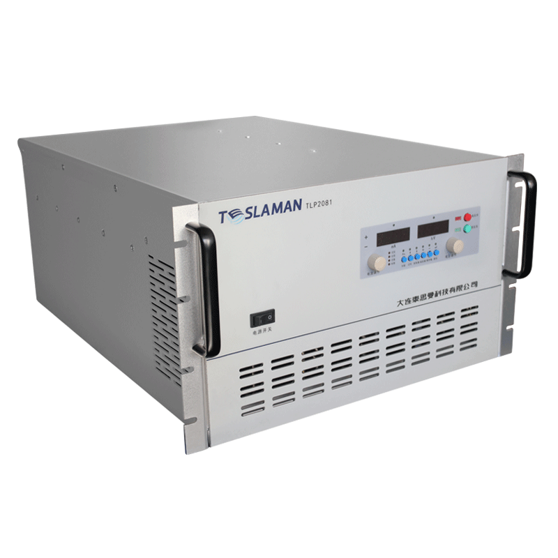
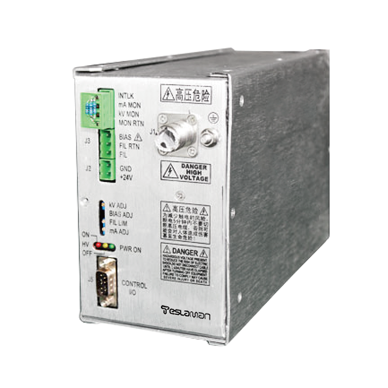
Dose Uniformity Control of Irradiation Sterilization High-Voltage Power Supply in Pharmaceutical Batch Processing
Dose uniformity control of an irradiation sterilization supply in pharmaceutical batch processing keeps the absorbed dose within the release range. The batch moves through the beam, the dose depends on the accelerator voltage and the beam current, and the uniformity is controlled by the supply and the conveyor.
The beam current stability sets the dose rate. The current is regulated against the line fluctuation, the dose rate is measured, and the conveyor speed matches the target dose.
The accelerating voltage stability sets the penetration. The voltage is held by the loop, the penetration depth is consistent, and the dose distribution across the package is uniform.
Batch processing demands the repeatable dose. The process recipe defines the voltage, the current and the speed, the recipe is loaded per batch, and the dose verification uses the dosimeter reading.
The supply supports the continuous operation. The thermal management keeps the temperature stable, the derating protects the stage, and the long-run output is monitored for the drift.
The interlock covers the conveyor and the radiation shield. The beam stops when the conveyor fault occurs, the shield status is confirmed, and the recovery follows the defined sequence.
Process verification uses the dose mapping. The dosimeters are placed across the batch, the measured dose is compared with the target, and the parameters are adjusted from the result.
Field maintenance focuses on the accelerator and the conveyor. The vacuum and the high-voltage state are checked, the trend data is reviewed, and the maintenance interval follows the record.
The gate drive is designed for the switching loss and the reliability. The drive voltage saturates the switch, the negative bias suppresses the false trigger, and the gate resistance matches the switching speed.
The high-voltage module equalizing design keeps the series voltage balanced. The equalizing resistor shunts the module, the unbalance stays within the limit, and the measured distribution confirms the design.
The ripple and the dynamic performance are a trade-off. The stronger filter reduces the ripple, the limited loop bandwidth slows the response, and the setting follows the application priority.
The protection threshold is set from the operating condition. The overvoltage threshold sits above the highest running voltage, the overcurrent threshold sits below the dangerous current, and the delay avoids the normal transient.
The insulation material is selected for the voltage and the temperature. The dielectric strength carries the margin, the thermal class matches the operating temperature, and the aging data supports the life assessment.
The control loop stability is verified by the phase margin. The compensation is set at the crossover frequency, the step response shows no oscillation, and the recovery time meets the load change requirement.
The high-voltage terminal design controls the discharge risk. The electrode chamfer reduces the field concentration, the insulation distance follows the withstand calculation, and the partial discharge test verifies the structure.
The efficiency depends on the topology and the device loss. The soft switching reduces the switching loss, the magnetic design optimizes the copper and the core loss, and the efficiency is measured at several load points.
The high-voltage switching sequence follows the safety order. The shutdown comes before the discharge, the discharge completion is confirmed, and the maintenance is permitted only after the confirmation.
The temperature sampling covers the critical device positions. The sensor layout follows the thermal analysis, the channels are calibrated, and the derating control uses the temperature data.
The galvanic isolation serves the insulation and the signal transfer. The optical isolation converts the low-voltage signal, the withstand voltage meets the standard, and the isolation performance is verified periodically.
The digital control keeps the hardware safety baseline. The hardware protection is independent of the software, the fast shutdown does not depend on the program state, and the abnormal path is verified.
The startup check covers the grounding and the interlock state. The ground resistance is confirmed, the interlock loop is tested, and the discharge path is verified before the power-up.
The ripple measurement excludes the external interference. The probe is grounded locally, the shield is complete, the bandwidth matches the indicator, and the repeated measurement is averaged.
The load characteristic affects the regulation. The capacitive load concerns the establishment time, the resistive load concerns the ripple, the pulsed load concerns the dynamic drop, and the field verification adjusts the setting.
The module temperature and the output capability are linked. The derating reduces the output at the high temperature, the derating curve follows the test result, and the rated operation returns after the condition recovers.
The field fault handling follows the symptom classification. The no-output case checks the supply and the protection, the output anomaly checks the feedback and the filter, and the insulation anomaly checks the environment and the aging.
The calibration is executed on the fixed schedule. The voltage and the current channels are calibrated point by point, the reference certificate is valid, and the deviation is corrected and re-verified.
The power-up self-test covers the critical paths. The sampling channel is verified, the protection logic is tested, the communication handshake is confirmed, and the abnormal item blocks the start.
The cable movement affects the measurement stability. The movement changes the distributed capacitance, the sampling chain receives the interference, and the fixed routing restores the repeatability.
The ambient temperature change causes the output drift. The compensation curve is generated from the measured data, the compensation covers the operating range, and the residual drift stays within the limit.
The high-voltage discharge test verifies the insulation margin. The test voltage rises by the standard step, the discharge level is monitored, and the breakdown point is located for the analysis.
The modular structure eases the maintenance. The faulty module is diagnosed independently, the spare stock follows the usage, and the replacement procedure is standardized.
The remote monitoring centralizes the management. The communication uses the unified protocol, the status data is uploaded in real time, and the alarm event is pushed with the record.
The inrush limiting protects the power-up. The limiting resistor and the relay cooperate, the inrush is measured, and the repeated start test verifies the repeatability.
The long-run attention is on the parameter drift. The output trend is recorded, the drift beyond the limit alarms, the aging is predicted, and the maintenance plan follows the data.
The field interference is located by the path analysis. The source is identified, the coupling path is analyzed, the shielding and the grounding are corrected, and the retest verifies the result.