








Dynamic Adhesion of E-CHUCK High-Voltage Power Supply in Advanced Chip and Flexible Display Manufacturing
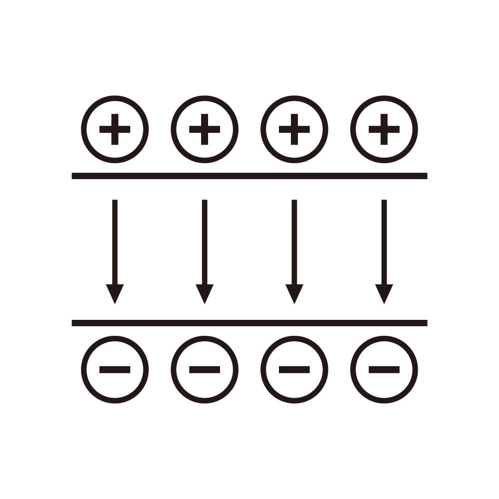
The dynamic adhesion of an E-CHUCK supply in advanced chip and flexible display manufacturing keeps the substrate fixed through the process step. The chuck and the display depend on the repeatable adsorption, so the supply holds the chuck voltage and the clamping is verified by the substrate flatness.
The chuck voltage stability sets the clamping force. The voltage is held by the loop, the force is repeatable, and the substrate stays flat through the step.
The multi-zone control compensates the substrate bow. The zones are adjusted independently, the flatness is recovered, and the process uniformity is maintained.
The de-chuck sequence releases the residual charge. The residual voltage is discharged, the release delay is bounded, and the transfer time is stable.
The insulation monitoring covers the chuck health. The leakage current is measured, the insulation state is tracked, and the maintenance is scheduled from the data.
The protection covers the chuck faults. The overvoltage and the overcurrent are handled, the electrode is protected, and the recovery follows the defined sequence.
The process verification uses the flatness and the overlay measurement. The result is compared with the target, and the zone voltage is adjusted from the data.
Field maintenance focuses on the high-voltage chain and the chuck state. The insulation and the clamping are verified periodically, and the anomaly is located from the record.
The transient control of the mode switch uses the ramp. The sudden change of the output parameter causes the overshoot, the ramp or the rate limit is added, and the transient is controlled.
The abnormal record during the test has the same value. The phenomenon, the action and the recovery are recorded, and the abnormal record is the material for the design improvement.
The first power-on check follows the fixed order. The wiring is checked before the power, the low voltage before the high voltage, the no-load before the loaded, and the reversed order causes the accident.
The parameter change during the field debug is kept. The content, the reason and the effect of the change are recorded, and the rollback and the trace are supported.
The re-test after the transport is not skipped. The vibration loosens the fastener and shifts the component, and the re-test items match the factory acceptance.
The long-running equipment gets the periodic inspection. The temperature, the noise, the vibration and the drift are recorded, the trend is built, and the anomaly is found early.
The test fixture life is managed. The worn fixture shifts the test result, the fixture is replaced by the count or the period, and the calibration verifies the state.
The environment condition during the test is recorded. The temperature and the humidity affect the insulation and the accuracy result, and the condition is written into the report.
The report conclusion corresponds to the data. The conclusion is derived from the data, the conclusion is not made from the incomplete data, and the data integrity is checked first.
The operator training follows the standard work instruction. The step, the criterion and the abnormal handling are consistent with the actual action.
The traceability system manages by the batch. The test data of each unit is linked to the serial number, and the problem is traced back to the specific batch and stage.
The field measurement of the power factor requires the calibrated wattmeter. The wattmeter is verified against the standard source, and the measured value is compared with the calculated value.
The load regulation measurement is done at the defined load step. The output change between the no-load and the rated load is recorded, and the regulation value is judged against the specification.
The test bench grounding and the shielding are done first. The interference enters through the ground loop and the space path, the bus bar cross section decides the reading stability, and the shield continuity decides the ripple measurement quality.
The calibration interval follows the usage frequency. The instrument used daily is calibrated every three months, the instrument used occasionally every six months, and the certificate is archived for the field trace.
The electronic load differs from the real load. The resistive load changes with the temperature, the electronic load carries the equivalent capacitance, and the conclusion is verified under both conditions.
The test cycle and the test depth conflict on the line. The tight cycle leaves the item untested, the long test cuts the throughput, and the failure risk decides the allocation between the line test and the sample test.
The aging condition follows the field data. The temperature, the humidity and the grid fluctuation are set from the record, the accelerated condition shows the real margin, and the distorted condition gives the useless life data.
The data recording habit decides the fault location speed. The voltage, the current, the temperature and the time stamp are recorded together, and the complete data chain is more useful than the later guess.
The spare part stock follows the module failure rate. The high-failure module is stocked more, the low-failure module less, and the balance is found between the capital and the downtime loss.
The field check starts from the supply source. The input waveform, the grounding state and the grid fluctuation are checked first, the source is clean before the equipment is examined, and the reversed order leads to the wrong judgment.
The repair record contains the phenomenon and the action. The same phenomenon may match different root causes, and the complete record builds the judgment experience.
The meter range is chosen with the margin in mind. The range close to the measured value saturates the reading, the range with too much margin loses the resolution, and the small deviation is missed.
The safety distance follows the voltage level. The higher voltage needs the larger distance, the fence and the warning sign are kept, and the emergency stop is placed within reach.
The contact resistance of the test lead and the fixture affects the result. The poor contact adds the drop into the reading, the fixture is cleaned and replaced periodically, and the contact state is checked by the drop method.
The temperature rise data of the aging test is judged at the thermal steady state. The temperature rises to the stable value before the record, the short energizing time gives the low rise and the optimistic conclusion.