







Standard rack-mount high-voltage power supplies in high-voltage test laboratories and standardized deployment
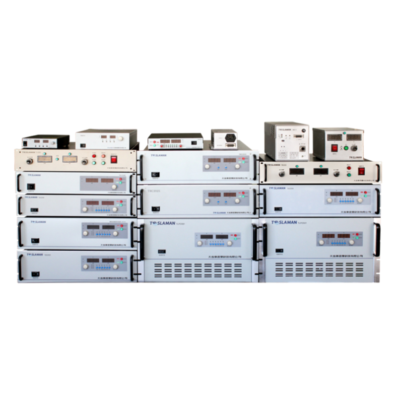
Commercial high-voltage test bays use rack-mount supplies, standardized in 19 inch rack chassis, 2 rack units tall. The supplies deliver 0 to 30 kV at 0 to 5 mA, with a USB control interface for automated testing. The test bay runs 24 hours per day, 6 days per week, testing customer products that range from capacitors to transformers. Each supply is assigned to a test station, and the station has a test fixture, a measurement instrument, and a safety interlock.
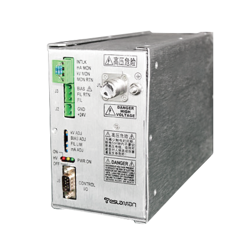
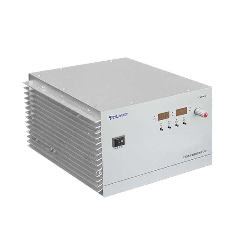
The rack-mount supply is 482 mm wide, 88 mm tall, and 350 mm deep, with a steel chassis. The front panel has a voltage display, a current display, a power switch, and a USB connector. The rear panel has the high-voltage output connector, the mains input, and a cooling fan. The supply weighs 8 kg, and is mounted on standard rack rails. The rack has 42 rack units of height, and holds 15 supplies, with space for patch panels and cable management.
The test procedure for each product is written in a test program, stored on the test bay computer. The program sets the voltage, the current limit, the ramp rate, and the hold time, and reads back the measured values. The test runs automatically, and the result is logged to a database. A typical test takes 5 minutes, including the ramp-up, the hold, and the ramp-down. The test bay runs 200 tests per day, across 15 stations.
The safety interlock on each test station is a light curtain across the fixture access area. The light curtain triggers a shutdown when a technician reaches in, and the supply output drops to zero within 20 ms. The residual charge on the output capacitor bleeds through a 10 MΩ resistor within 100 ms. The light curtain once tripped by accident when a technician leaned over the fixture, and the test was interrupted. The light curtain sensitivity was adjusted to ignore a slow lean-over, and the false trip has not recurred.
The high-voltage output connector is a SHV type, rated for 5 kV and 5 A. The connector mates with a fixed receptacle on the test fixture. The contact surface is gold-plated, and the plating wears through after 500 mate cycles. The connector is replaced preventively at 500 cycles, before the plating wears through. The mate cycle count is logged on the connector body, with a date tag and a cycle counter.
The supply cooling is by a rear fan, pulling air through the chassis from front to rear. The fan runs continuously when the supply is powered, at a fixed speed. The fan noise is 45 dB at 1 m, measured with a sound level meter. The fan once failed, and the supply temperature reached 60 degrees, triggering the thermal shutdown. The fan was replaced within 30 minutes, and the supply returned to service. The fan is now replaced preventively at 30000 hours, as a safety margin.
The supply calibration is done quarterly, against a 0.1 percent standard divider. The calibration procedure is written in the quality manual, and the calibration record is filed in the quality system. The calibration drift over 12 months was 0.2 percent, equivalent to 60 V at 30 kV. The drift is within the 1 percent acceptance limit, and the supplies are scheduled for recalibration at the 24 month mark, when the drift is projected to cross 0.5 percent.
The test bay environment is held at 23 plus or minus 2 degrees Celsius, with 40 to 60 percent relative humidity. The bay has a dedicated air conditioning unit, with the airflow directed away from the test stations. The bay illumination is 500 lux, with dimmable LED fixtures. The bay has a sign on the door, warning of high voltage. Entry requires a sign-in log, and non-authorized personnel are not permitted.
The maintenance log lists routine tasks. Each shift, the operator records the test count and the supply status. Weekly, the technician inspects the connectors and the fan filters. Monthly, the insulation resistance is measured with a 1000 V megohmmeter. Quarterly, the supplies are calibrated. Annually, the fan filters are replaced. The log is signed at each step, and the record is filed in the quality system.
The input side of each supply draws 230 V single phase at 2 A. A 5 kVA isolation transformer sits in the rack, serving all 15 supplies. The isolation transformer has a 1500 V insulation rating between primary and secondary. The input cable is copper, 2.5 mm², rated for 16 A, routed along the rack cable management. The input breaker is a 16 A miniature type, with a thermal-magnetic trip. The input power factor is 0.95, measured with a power analyzer during commissioning.
The high-voltage transformer inside each rack-mount supply is epoxy potted, with no oil volume. The potting material is epoxy resin, and the transformer is fully sealed. The transformer temperature reaches 40 degrees after 8 hours of continuous operation at 30 kV and 5 mA, against an ambient of 25 degrees. The potting material has a thermal conductivity of 0.8 W per m per K, and the heat is conducted to the chassis. The transformer sound level is 40 dB at 1 m, measured with a sound level meter.
The output divider inside each supply is a series chain of 100 MΩ high-voltage glass glaze resistors, totaling 1 GΩ. The divider tap at 1:1000 feeds the control board ADC. The divider is calibrated quarterly against a 0.1 percent standard divider. The calibration drift over 12 months was 0.2 percent, equivalent to 60 V at 30 kV. The drift is within the 1 percent acceptance limit, but the dividers are scheduled for resistor replacement at the 24 month mark.
The test fixture for each station is custom built for the customer product. The fixture has a high-voltage contact, a ground contact, and a temperature sensor. The fixture is mounted on an adjustable table, and the product is positioned by hand. The fixture interlock trips the supply when the product is not seated, preventing an open-circuit test. The fixture is cleaned weekly, and the contacts are inspected for wear.
The measurement instrument for each station is a digital multimeter, 6.5 digit, measuring the output voltage and current. The multimeter is connected to the test bay computer via USB, and the readings are logged to the database. The multimeter is calibrated annually, against a 0.01 percent standard. The calibration record is filed in the quality system. The multimeter uncertainty is 0.01 percent, and the total measurement uncertainty, including the supply divider, is 0.1 percent.
The customer acceptance test was run over two days. Day one covered the supply performance, measuring the voltage accuracy, the ripple, and the transient response. Day two covered the test bay operation, running 100 automatic tests and verifying the data logging. The test report was signed by the customer representative, and the test bay entered the 12 month warranty period.
The test bay layout has 15 stations, arranged in three rows of five. Each station has a rack-mount supply, a test fixture, a multimeter, and a computer monitor. The stations are numbered 1 to 15, and the number is displayed on the station front. The station assignment is based on the customer product type, and the assignment is tracked in the database. The stations are connected to the network by Ethernet, and the test data is sent to a central server. The server backs up the data weekly, and the data retention policy is 5 years.
The safety interlock on the test bay entrance was tested during commissioning. The bay door has a magnetic contact, and opening the door triggers a shutdown of all supplies. The shutdown response time is 20 ms, and the residual charge on all output capacitors bleeds through the 10 MΩ resistors within 100 ms. The interlock response time was logged at 18 ms, within the 25 ms design limit. The bay door carries a high voltage warning label, and entry requires a sign-in log. The non-authorized personnel are not permitted inside the test bay.
The test bay data system runs on a central server, with 15 client computers at each station. The server stores the test programs, the test results, and the calibration records. The server is backed up nightly, and the backup is stored offsite. The data system is accessed by the quality department, which reviews the test results and the calibration status. The data system generates monthly reports, showing the test throughput, the failure rate, and the calibration status. The reports are distributed to the plant manager and the customer quality department.
The test bay safety audit is conducted annually, by an external safety consultant. The audit covers the electrical safety, the mechanical safety, and the chemical safety. The audit report lists the findings, and the corrective actions are scheduled within 30 days. The last audit found two minor findings: a missing label on one high-voltage connector, and a worn gasket on one cabinet door. Both findings were corrected within the scheduled time. The audit record is filed in the quality system.
The test bay spare parts inventory includes: high-voltage connectors, fan filters, fuses, and calibration dividers. The inventory is stocked at 20 percent of the annual consumption, and is reviewed monthly. The inventory is stored in a locked cabinet, and the key is held by the test bay supervisor. The parts are logged out when used, and the log is reviewed by the quality department. The inventory was once depleted when a batch of connectors failed, and the stock was replenished within 3 days.
The test bay operates three shifts per day, 6 days per week. The day shift runs the routine production tests, the evening shift runs the batch tests, and the night shift runs the maintenance and calibration. The shift handover includes a status report, listing the completed tests, the failed tests, and the pending maintenance. The handover log is reviewed by the test bay supervisor, who allocates resources for the next shift. The shift schedule is published monthly, and the operators are trained on the test procedures.
The test bay qualification is per ISO 17025, with the test procedures documented and the equipment calibrated. The quality manual describes the test procedures, the calibration schedule, and the record keeping. The test bay is audited annually by an external accreditation body, and the audit report is filed in the quality system. The accreditation is renewed every 5 years, and the renewal audit is conducted by the accreditation body. The test bay has maintained the accreditation for 8 years, with no major findings in the last 3 audits.
The test bay computer system is maintained by the technology department, with weekly backups and monthly software updates. The test programs are version controlled, and the version history is tracked in the quality system. The test data is stored on a redundant array of independent disks, with weekly offsite backup. The computer system has a 99.9 percent uptime target, and the downtime is logged in the maintenance record. The system once had a hard disk failure, and the redundant array rebuilt the disk within 4 hours, with no data loss.
The test bay operator training is conducted by the quality department, with a 40 hour course covering the test procedures, the safety rules, and the equipment operation. The operator must pass a written exam and a practical exam, before being authorized to run the tests. The operator certification is renewed annually, with a refresher course. The training record is filed in the quality system, and the certification cards are carried by the operators. The training has been conducted for 8 years, and 25 operators have been certified.
The test bay has a serial number plate on each supply, with the model number, the serial number, the manufacturing date, and the electrical rating. The plate is stainless steel, engraved, and bolted to the supply front panel. The plate is checked annually, and the information is verified against the purchase order. The supply has a warranty label, with the warranty period and the contact information for the service department. The label is affixed to the front panel, and is visible from the operating position.
The test bay has run for 24 months. The rack-mount supplies have accumulated 15000 hours each. The connectors have been replaced once, at 500 mate cycles. The fans have been replaced once, at 30000 hours. The unresolved issue is the USB control interface reliability. The interface once dropped connection mid-test, and the test was interrupted. A more reliable Ethernet interface is under evaluation, and the upgrade is scheduled for the next supply revision.