Stable control of electrostatic chuck high-voltage power supplies in ion etching chambers and long-duration chucking
The electrostatic chuck sits on the dielectric etch pedestal and holds 300 mm wafers through main-etch steps that run 90 to 180 seconds per wafer at chamber pressure of 4 to 8 mTorr. The chucking supply feeds a single ceramic body through a pair of interdigitated electrodes, setpoint 1200 V, drawing between 0.15 and 0.35 mA once the wafer lands. Helium backside cooling flows at 10 Torr center and 5 Torr edge, and the pedestal holds 65 degrees Celsius through the etch. Voltage ramp reaches 1100 V within 80 ms of wafer clamp, then plasma strikes. Any overshoot past 1350 V trips the supply and aborts the chamber, so the loop gain stays deliberately low on the ramp slope. The supply cabinet sits in the sub-fab on a dedicated 208 V feed, and the HV line runs 6 meters from deck to pedestal through a shielded flexible conduit. Output ripple measured at the chuck flange stays under 1.2 V peak to peak at 1200 V setpoint, which matters because ripple at the wafer back couples into the plasma sheath as a 20 kHz amplitude modulation. The grounding strap between pedestal wall and chamber frame was re-bonded after an infrared scan showed a 14-degree Celsius hot spot at the joint. The strap swap took 3 hours and required a chamber vent, so the work got bundled into the quarterly maintenance block.
Long chucking across a 120-hour production run changes the picture. Leakage current on a fresh chuck sits near 0.2 mA at 1200 V. After 3000 wafer passes, fluoropolymer byproducts deposit on the ceramic skirt and the creepage path shortens, so the same voltage pushes 1.6 to 2.1 mA through the surface. The supply holds regulation, but the force budget drops. Chucking force near 300 Torr equivalent pressure early in the run falls toward 180 Torr by the 3000th wafer, enough to let the wafer lift 20 micrometers at the edge during high-power dielectric etch. Helium leaks upward into the plasma, the wafer cools unevenly, and etch rate drifts 8 percent across the radius. The maintenance team now watches the leakage trend line once per shift rather than waiting for a trip. The measurement comes from the supply internal shunt, sampled at 10 Hz, and the trend file feeds the fab equipment monitor. A second check with a handheld microammeter on the pedestal tap matches within 0.03 mA, so trust in the internal number is high enough for production decisions. When the trend crosses 1.2 mA, the chamber enters a watch list; at 2.0 mA, a preventive skirt clean gets scheduled before the next wet close. The old rule, a hard trip at 3 mA, produced too many unplanned stops, each one costing about 45 minutes of pump and seasoning time. The trend file resolution, 0.01 mA per sample, catches the slow rise three shifts before a trip would occur.
De-chucking exposes a different fault. After main etch, wafer surface charge remains trapped in the oxide layer at 60 to 90 V, and the standard sequence drops chucking voltage to zero, pumps helium out, then transfers. Residual charge holds the wafer to the ceramic, the robot picks at one corner, and the wafer cracks or slips. The fix adopted on most chambers applies a reverse bias pulse of minus 400 V for 150 ms before the ramp to zero, then a 50 ms float. Residual drops below 30 V in bench checks, though at production temperature 70 degrees the drift back to 45 V happens inside 10 seconds. Transfer timing was tightened to a 3-second window after pulse end to catch the low-residual moment. Wafer breakage fell from one in 400 transfers to one in 9000 after the change. The residual voltage is read by a capacitive sense pad under the chuck center, sampled with a 12-bit ADC at 1 kHz. Before the pulse logic, the sense pad showed 60 to 90 V at transfer; now the transfer interlock refuses the robot command if residual reads above 25 V. A failed interlock on two chambers last year traced to a cracked sense pad cable insulation, which read a constant 10 V and let the robot proceed on a truly charged wafer. The cable runs along the pedestal bellows and flexes with every wafer swap, so the harness was rerouted with extra slack and scheduled for replacement on the 12-month inspection.
Spike trips cluster around wafer transfer rather than etch. When the wafer lifts 0.5 mm off the chuck while voltage still sits at 200 V, the narrow gap ionizes and a micro-arc fires. Each spike dumps about 0.08 J, well under the 0.5 J threshold that damages the focus ring coating, but the trip log fills with nuisance faults. A software fix delays helium vent until the voltage crosses 50 V, and the spike count per day drops from 14 to 2. The remaining arcs happen during chamber seasoning, when the wall coating turns conductive after a wet clean and the first 50 wafers run at reduced chucking voltage of 900 V to avoid edge breakdown. Operators leave that seasoning recipe unchanged even though the throughput cost is about 3 percent on those days. The spike detector inside the supply trips on a dVdt above 5 V per microsecond at the output terminal, and the shutdown sequence cuts the HV enable within 4 microseconds. Oscilloscope captures during nuisance spikes show a 30 ns rise to 400 V across the gap, ringing down over 2 microseconds. Raising the detection threshold to 8 V per microsecond was tried once, and a real arc on a poisoned target burned through the ceramic edge seal before the trip caught the event. The threshold went back to 5. The nuisance spikes cost about 10 minutes of restart time per day, and the line accepted that cost over the risk of a missed real arc.
Ceramic refurbishment drives the real cost. Every 18 months, the chuck comes out for alumina re-coating and skirt cleanup. Leakage at that point has climbed to 4 mA, and the surface resistance has fallen from 50 gigaohm to 4 gigaohm measured at 500 V between the electrode and ground. Refurbishment runs 36 hours out of production and costs more than the supply. Between overhauls, a quarterly wipe with isopropyl alcohol on the skirt extends the interval by about three weeks, but the center contact pins resist cleaning and still need replacement every 4000 hours. The pin seats hold 6 independent temperature zones, and a single pin fault on the edge zone shifts the backside gas distribution enough to show up as a 10 nanometer CD shift on outer-ring features. The pin replacement takes 4 hours per chuck and requires a full chamber open, so the line batches the work with the scheduled pump-down for other reasons. Surface resistance measurements after refurbishment come back near 60 gigaohm, and the first weeks of the new cycle run leakage under 0.25 mA. The re-coating vendor quotes a tolerance of 15 micrometers on the alumina thickness, and out-of-spec thickness causes a 12 percent spread in chucking force measured across the wafer. One batch in 2024 came back thin and showed weak edge hold, requiring a second recoat before install. The second recoat added 24 hours of delay, and the vendor contract now includes a thickness re-check clause before shipment.
Endpoint detection interacts with chucking in ways the recipe book does not cover. The optical emission endpoint window runs 5 seconds at the end of the etch, and the plasma power drops 30 percent during the window. The lower power lets the wafer cool 8 degrees, and the thermal contraction shifts the wafer on the chuck by a few micrometers. The shift shows up as a faint scraping sound at the end of the window, heard on the chamber acoustic monitor. When the chucking force dropped late in a run, the scraping turned into a visible slip on the outer ring, and two wafers showed scratched patterns at the edge. The recipe team raised the helium pressure 1 Torr edge during the endpoint window to hold the wafer flat, and the scraping stopped. The extra helium costs 0.05 percent of throughput, and nobody tracks the gas bill closely enough to notice. The acoustic monitor data, stored in the fab database, shows the scraping frequency rising from 0.2 events per wafer at the start of a chuck cycle to 1.5 events per wafer at the end, which mirrors the leakage trend line.
Parameter tuning went through three versions before the current setup. First revision raised chucking voltage to 1500 V to compensate force loss late in the run, but edge arcs rose fourfold and the ceramic showed partial discharge above 1400 V at 70 degrees. Second revision cut helium pressure to 3 Torr edge to stop upward leakage, and wafer temperature rose 11 degrees, pushing photoresist char on the edge die. The current compromise sits at 1200 V, 10 Torr center, 5 Torr edge, plus a leakage alarm at 2.5 mA that triggers a preemptive skirt clean. Force budget still ends the run at 170 Torr, and nobody on the floor calls the problem fully solved. The trade accepted is a lower force floor in exchange for zero arc trips during etch. Partial discharge measured with an ultrasonic sensor at the ceramic edge reads 12 pC at 1200 V and 70 degrees, and the alarm threshold sits at 50 pC. At 1500 V the same sensor read 90 pC on a refurbished chuck, which is why the voltage ceiling stays at 1200 V and no further upward step is planned. The helium pressure trade cost edge die yield on two product layers, so the pressure came back up and the voltage stayed down. Engineers on the line would rather lose a few millitorr of cooling margin than risk a chamber down event on a wafer lot already past rework.
Weekend unattended runs still show one anomaly. The leakage baseline drifts upward overnight on humid days, climbing 0.4 mA per 24 hours when the fab humidity runs above 55 percent. A 12-hour standby at 40 degrees pedestal temperature restores part of the margin, and the maintenance log blames surface moisture on the ceramic skirt absorbing atmospheric water during load-lock cycles. Nitrogen purge on the front opening unified pod reduced the drift by half, and a full purge retrofit on the load lock was quoted at 80000 dollars per chamber. The line ran three chambers with the retrofit and left nine without. Long-duration chucking stability, in the end, tracks more closely with ambient humidity than with anything inside the supply cabinet. On days when the fab humidity climbs past 60 percent, the overnight leakage reaches 2.8 mA and the morning shift starts with a preemptive clean rather than waiting for the alarm. The humidity sensor sits outside the chamber in the sub-fab aisle, and one chamber reads 10 points higher than the others because the load lock door seal leaks slightly. The seal stayed on the replacement list for two quarters. Budget cycles on the retrofit keep sliding, and the drift problem stays half-solved on the nine unmodified chambers.
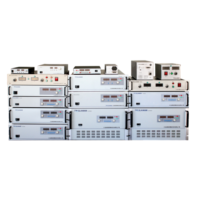
The supply cabinet draws little attention once the loops settle. Input power stays near 180 W at full chuck, and the internal toroidal regulator runs at 22 kHz. Output monitoring logs voltage, current, temperature, and trip count to the fab database every 60 seconds. The fan on the cabinet intake runs at 1800 rpm and was replaced twice in three years after dust buildup in the sub-fab choked the airflow. Cabinet internal temperature sits at 38 degrees Celsius under load, 5 degrees above the design target, and the fan curve was re-parameterized to 2400 rpm to bring the reading down. A spare exchange unit sits on the shelf calibrated within 50 mV at 1200 V, and swap time inside the cabinet is under 2 hours including leak check of the helium lines. The HV connector at the pedestal uses a finger-proof shroud, and the interlock loop trips the 24 V enable the moment the chamber door unlocks. Door interlock bypass, once used during seasoning by mistake, caused one uncontrolled ramp to 900 V into an open chamber in 2023. The bypass switch was removed from the panel after that event. The cabinet alarm log, reviewed weekly, shows one or two nuisance alarms per month, all on the leakage trend crossing the watch threshold briefly before recovering.
The load-lock door seal replacement finally happened at the end of the last budget cycle. The seal, a 3-meter circular gasket 8 mm in cross section, cost 420 dollars and took 6 hours of downtime. After the replacement, the chamber humidity reading dropped 8 points, and the overnight leakage drift fell from 0.4 mA to 0.15 mA. The morning shift no longer starts with a preemptive clean on that chamber. The other nine chambers keep sliding on the list, and the drift problem stays on nine of ten. The replacement part, ordered from the gasket vendor in 6 mm EPDM stock, arrived in 5 days, and the install crew booked the work into the weekend maintenance block. The old seal, peeled off the door groove, showed a flattened cross section of 6 mm instead of the spec 8 mm, and the compression set measured 35 percent on the Shore A 60 scale.