






Adsorption Reliability of Electrostatic Chuck High-Voltage Power Supplies in Precision Stages and Wafer Transfer
An electrostatic chuck running at five hundred volts of clamping bias keeps a three hundred millimetre wafer flat during exposure, and the whole lithography cycle depends on that clamp never hesitating. The chuck is a dielectric layer of alumina a few hundred micrometres thick, the electrode sits underneath, and the supply has to deliver a clean, repeatable voltage within tens of milliseconds of the wafer landing. Adhesion failure does not announce itself as a power supply fault. It appears as a wafer that slides two micrometres during acceleration, or as a chuck that refuses to release until the wafer is prised off by a transfer arm.
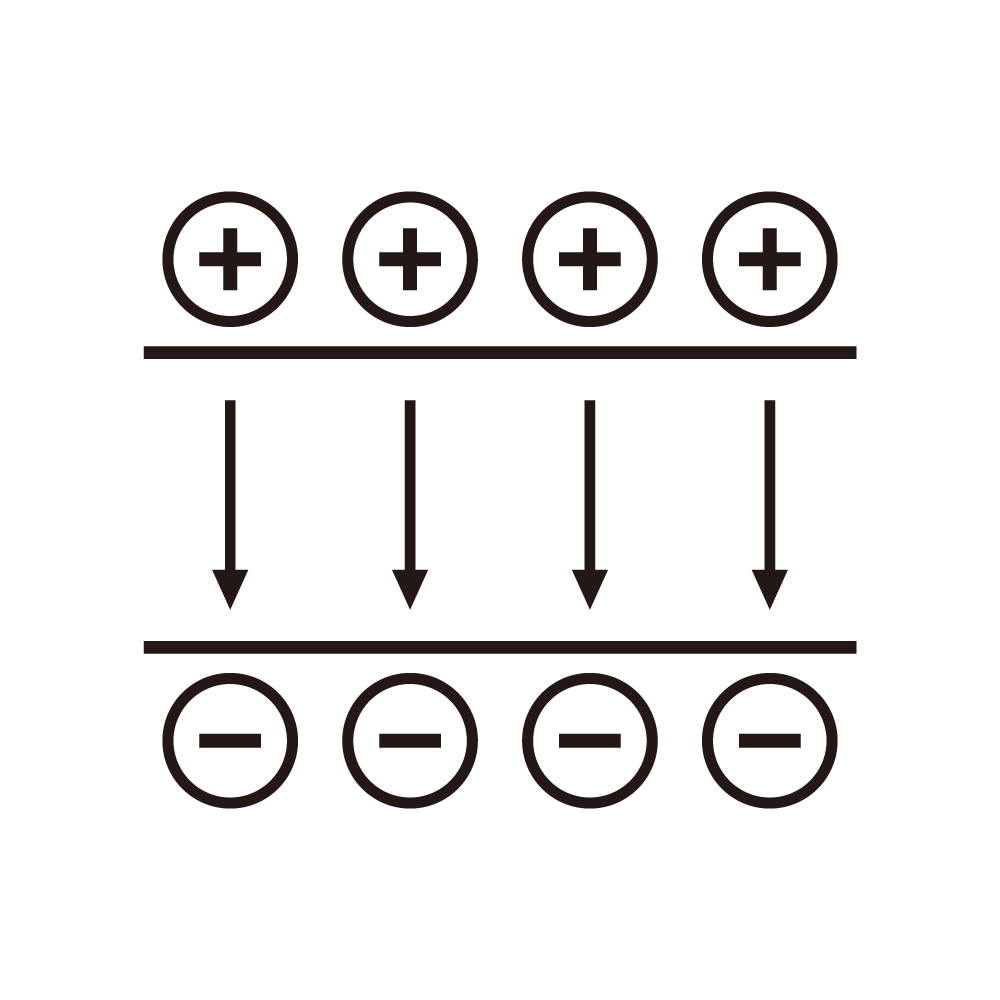
Reliability starts with the load model. Electrically the chuck is a capacitor of two to eight nanofarads in series with a leakage resistance that depends on dielectric quality, temperature and the residual gas in the chamber. At low humidity the leakage resistance can exceed one hundred teraohms, and at high humidity with a contaminated surface the resistance falls by several orders of magnitude. A supply designed for one end of this range behaves badly at the other. Charge-up at the dry end is slow, release at the wet end is slow, and both appear as intermittent transfer faults.
Clamping voltage has to be programmed rather than switched. A relay that connects a fixed voltage to the chuck produces a step with contact bounce, and bounce during charge-up can leave a partial clamp that looks stable on the meter but slips under acceleration. A programmable output ramps to the clamping value at a controlled slope, typically two hundred volts per millisecond, holds for the full process window, and then ramps down before release. The ramp shape matters more than the final value.
Bipolar clamping removes a problem that unipolar clamping keeps. With a single polarity, charge accumulates on the dielectric surface and the residual clamp persists after the output is removed. Reversing the polarity for a short interval before release neutralises the surface charge, but the reversal has to be controlled in amplitude and duration. Too short and the wafer stays stuck, too long and the wafer begins to move before the lift pins are up.
The supply needs to measure charge, not just voltage. Current integration during charge-up gives the delivered charge, and comparing that with the expected value for a given chuck capacitance tells whether the dielectric is intact. A chuck with a crack or a delaminated layer draws more charge than nominal, and the wafer clamps unevenly. Supplies that only regulate voltage hide this failure until the wafer is scrapped.
Transfer reliability also depends on the release sequence. The output must fall to zero while the lift pins are still retracted, then the pins rise and the wafer is lifted while the chuck is at zero. If the pins rise before the output reaches zero, the wafer is pushed against the clamp and either breaks or slides. The interlock between the supply and the pin mechanism has to be at the level of measured voltage, not at the level of a command acknowledgement.
Repeatability across thousands of cycles is the real test. A chuck that clamps correctly on the first hundred wafers and drifts on the thousandth is worse than a chuck that fails immediately, because the failure is buried in process data. Monitoring of charge delivery and release time per cycle, with statistical limits, catches the drift before it reaches the wafer.
Humidity control is part of the electrical design. A supply installed in a chamber held at forty percent relative humidity behaves differently from one in a cleanroom at twenty percent. Surface leakage on the chuck and on the high-voltage feedthrough changes the charge and release times. Specifying the supply for the humidity range of the installation, and recording it in the process recipe, prevents a recipe that works in one bay from failing in another.
Cable capacitance between the supply and the chuck is not negligible. A one-metre high-voltage cable adds fifty to eighty picofarads, which is comparable to the chuck itself. The supply sees the sum, so the charge delivered is higher than the chuck needs, and the release time is longer than expected. Compensation is possible either by measuring at the chuck end or by characterising the cable and correcting the charge target.
Feedthrough design affects both reliability and measurement. A ceramic feedthrough with a guarded ring keeps surface leakage out of the current measurement, while a simple epoxy potted feedthrough allows leakage to bypass the measurement and makes charge delivery look smaller than actual. Guarding costs a few millimetres of space and solves a class of measurement errors that otherwise take weeks to diagnose.
Release failure has a characteristic signature. The chuck voltage reads zero, the pins rise, and the wafer does not move; a light push frees it. The cause is residual charge on the dielectric, and the cure is a controlled reverse pulse followed by a dwell. Supplies without this function force operators to improvise, and improvised sequences damage wafers and pins.
Overvoltage during clamping is more dangerous than undervoltage. A supply that overshoots by ten percent on a thin dielectric raises the electric field close to breakdown, and a single breakdown damages the chuck permanently. The output filter and the loop damping must be designed so that the worst-case overshoot stays below three percent, including the case where the chuck is disconnected during the ramp.
Thermal drift of the voltage divider is a slow source of misalignment. The divider sits near the chuck, which is heated by the process, and a temperature coefficient of twenty-five parts per million per kelvin across a fifteen-degree gradient shifts the reading by almost four hundred parts per million. Correcting with a temperature sensor at the divider, or moving the divider away from the heated zone, keeps the reading honest.
Diagnostics should distinguish chuck faults from supply faults. Charge delivery low with voltage normal points to a chuck or cable problem; charge delivery normal with voltage sagging points to a supply problem; both low with leakage high points to contamination. A supply that reports only a generic clamp fault leaves the diagnosis to guesswork at a cost of several hours per event.
Availability matters more than peak performance in a fabrication line. A supply that needs recalibration every month, or that trips on transients and requires a manual reset, will be bypassed by operators and eventually replaced. Watchdog behaviour, automatic recovery from a single transient, and a clear alarm history are worth more than an extra decimal place of regulation accuracy.
Cost of the clamp function is small compared with the cost of a mis-clamped wafer. The supply itself is a minor line item, but the interlocks, the charge measurement, the reverse pulse function and the diagnostics add engineering content that is easy to cut during procurement. Cutting them shifts the cost to yield, where it is much harder to see.
Limits deserve a place in the specification. The behaviour at very low humidity, the behaviour with a contaminated chuck surface, and the behaviour after a dielectric breakdown are all outside the normal operating envelope, and no supply can guarantee recovery from a damaged chuck. Defining what the supply will and will not tolerate keeps expectations aligned with physics.
A practical acceptance test can be built from ordinary equipment. Charge and release times measured over fifty cycles, at two humidity levels, with and without the cable installed; overshoot measured with the chuck disconnected mid-ramp; leakage measured with the chuck at temperature. Four measurements, half a day, and a supply whose reliability in transfer is no longer a matter of opinion.
Clamping while the stage is moving adds a requirement that is easy to miss. Acceleration of the stage produces a lateral force on the wafer, and the friction that resists it is proportional to the clamping pressure, which is proportional to the square of the voltage. A supply whose output sags during the acceleration phase, even by three percent, reduces the friction by six percent, and a wafer already at the edge of slipping will slip. Output impedance under load steps is therefore a transfer reliability parameter, not a regulation nicety.
Voltage monitoring at the chuck rather than at the supply removes another class of error. A divider installed inside the supply reads the voltage at the output terminal, but the chuck end sees less because of cable drop during charge transients. Over a hundred thousand cycles the difference is invisible in the mean and visible in the tails, which is where wafers are lost. A remote sense pair, guarded and shielded, closes the gap.
Maintenance intervals should follow measured behaviour. Divider calibration once a year, cable inspection once a quarter, feedthrough cleaning on the same schedule as the chamber, and a full charge and release characterisation after any component replacement. Replacing a feedthrough without repeating the characterisation is the most common way a line loses a working recipe.
There is a boundary that no supply can cross. A chuck whose dielectric has absorbed moisture cannot be made reliable by increasing voltage, and a feedthrough with a surface track cannot be cured by cleaning alone. Recognising when the problem has moved from the electrical domain to the materials domain saves weeks of pointless adjustment.
Replacement decisions benefit from a simple record. Charge delivered per cycle, release time per cycle, humidity, and any overvoltage event, kept for the life of the chuck. When transfer faults begin, the record shows whether the supply changed behaviour or the chuck did, and that distinction is usually the whole diagnosis.