











Pulsed Energy Release and Packaging of High-Voltage Power Supplies for Pulsed Industrial Loads
Industrial pulsed loads, whether electrostatic precipitators, pulsed plasma surface treatment, capacitor charging for forming or pulsed electric field food processing, share a common electrical shape: energy is stored slowly and released quickly, and the supply's job is to refill the store between pulses without disturbing the process or itself. The packaging is where the design usually fails, because the same enclosure holds the energy storage, the switch, the charging converter and the control electronics, and each of those objects interferes with the others.
Capacitor charging is the simplest case and establishes the parameters. A store of a few microfarads charged to fifty kilovolts holds several joules, and a repetition rate of ten pulses per second requires an average power of tens of watts with a peak charging current of amperes. The supply's output filter and its current limit determine the charging time, and the charging time sets the maximum repetition rate.
Release is the demanding part. The switch, whether a spark gap, a thyristor stack or a semiconductor switch, has to conduct a current that rises in nanoseconds and falls in microseconds, and the current path's inductance determines the voltage overshoot across the switch. Packaging that puts the switch far from the store adds inductance and produces an overshoot that destroys switches which would otherwise survive.
Loop inductance is a packaging parameter, not a circuit parameter. A discharge loop with a hundred nanohenries and a current rise of ten thousand amperes per microsecond develops a volt across the loop, and at fifty kilovolts that is negligible; with a microhenry the same rise develops ten volts, still small. The overshoot becomes dangerous when the switch interrupts the current, because the stored magnetic energy has nowhere to go.
Snubber design should be distributed rather than centralised. A single snubber across the switch carries the full loop current and must be physically large; small snubbers distributed along the busbar carry a fraction each and reduce the local overshoot. Distributed snubbers are harder to design and much easier to package into a confined space.
Charging converter packaging determines the supply's own noise. A converter switching at fifty kilohertz inside the same enclosure as the discharge circuit radiates into the trigger electronics, producing spurious triggering that appears as an erratic pulse rate. Separating the converter's loop from the discharge loop, shielding the trigger, and placing the trigger's ground reference at the switch rather than at the converter, removes most of the coupling.
Insulation coordination in a pulsed enclosure is dominated by the electric field's distribution rather than by the average stress. A busbar edge concentrates the field, and a dielectric with a high permittivity in a non-uniform field experiences partial discharges at voltages well below the average breakdown. Rounding edges, grading the field with a conductive layer, and keeping the dielectric's thickness proportional to the local field are the practical measures.
Dielectric selection for the store is a trade between energy density and lifetime. A film capacitor with a self-healing dielectric tolerates occasional breakdown but has lower energy density; a ceramic has higher density but fails shorted and takes the switch with it. For industrial repetition rates, film capacitors dominate, and their lifetime is quoted in charge-discharge cycles that must be translated into calendar life for the application.
Thermal design in a pulsed enclosure is about average power, not peak. A store that releases ten joules per pulse at ten pulses per second dissipates heat in the dielectric proportional to the loss tangent, and the switch dissipates heat proportional to the charge transferred. The enclosure's cooling must handle the average, and the internal temperature rise affects the dielectric's lifetime and the switch's timing.
Packaging for serviceability is a constraint that is often sacrificed and later regretted. A capacitor bank that cannot be accessed without removing the switch doubles the downtime for a single failed capacitor. Modular construction, with the store in removable trays and the switch on a separate busbar, allows a failed unit to be replaced in an hour instead of a day.
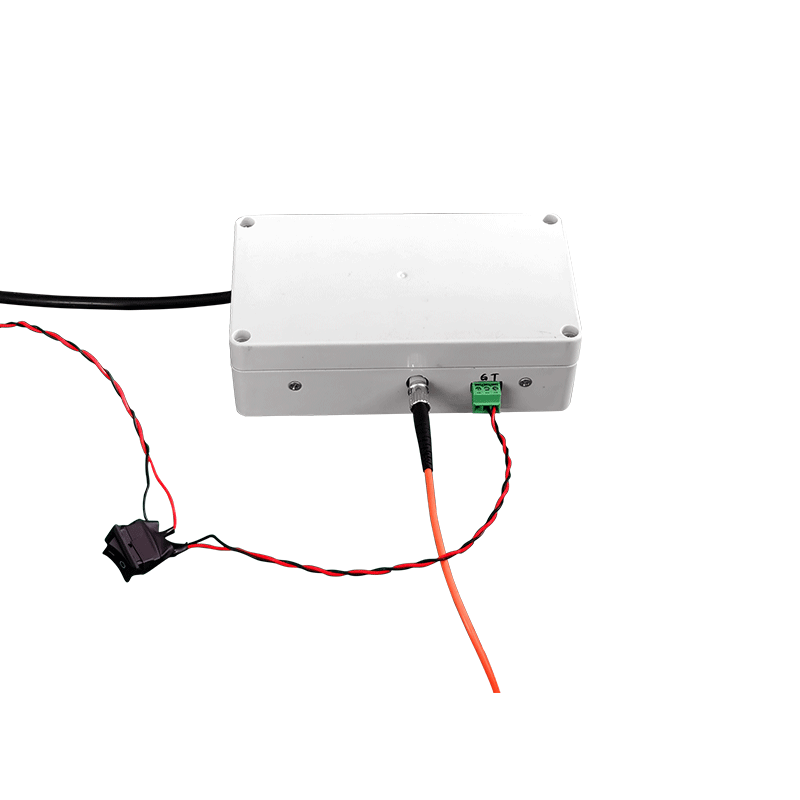
Measurement inside a pulsed enclosure requires isolation that survives the pulse. Voltage probes must have a bandwidth well beyond the pulse's rise time, and current probes must be immune to the common-mode transient that accompanies the discharge. Fibre-linked probes, with the electronics in a shielded box, are the only reliable option at these amplitudes.
Safety interlocking for a pulsed store has a specific hazard that steady-state supplies do not: the store remains charged after the supply is switched off, and a failed dump circuit leaves it charged indefinitely. A dump relay with a mechanically verifiable action, a voltage indicator that is checked before access, and a discharge stick for the case where the dump has failed, together form the minimum safe arrangement.
Electromagnetic emission from a pulsed enclosure is broadband, and the enclosure's seams are the weakest point. A seam with a gasket attenuates by tens of decibels; a seam with a painted flange attenuates by nothing. Removing paint at the flange, using a conductive gasket, and bonding the cover with a screw pattern dense enough to keep the seam's length short are details that decide whether the enclosure complies.
Cost trade-offs in pulsed supplies favour investment in packaging over investment in the converter. A converter that is ten percent more efficient saves modest energy; a package that halves the loop inductance eliminates a class of switch failures. The parts that cost money are the busbar geometry, the dielectric grading and the serviceable modules, and they are the parts that determine reliability.
Limits should be clear. The repetition rate is limited by the charging power and by the store's thermal capacity, and no packaging cleverness changes those. Similarly, the pulse's rise time is limited by the switch and the loop inductance; a faster rise requires a different switch, not a different enclosure.
An acceptance test that exercises the packaging is the pulse test at the specified repetition rate. Run a thousand pulses into a dummy load, measuring the switch's peak voltage, the store's temperature, the radiated field at the enclosure's surface, and the trigger's false-trigger count. A thousand pulses is enough to reveal a marginal snubber, an undersized thermal path, and a coupling problem that only appears when the converter and the switch operate together.
Trigger reliability is a system property that the packaging decides. A trigger transformer mounted far from the switch adds cable capacitance that slows the trigger's rise, and a switch that fires late produces a jitter that appears as pulse-to-pulse energy variation. Mounting the trigger at the switch, with a short, low-inductance connection, is a mechanical decision with direct electrical consequences.
Capacitor life should be tracked by charge transferred rather than by calendar time. A store operating at ten pulses per second transfers a large charge each day, and the dielectric's ageing is proportional to that charge. A counter in the controller that accumulates delivered charge and compares it with the manufacturer's rating gives a replacement date that is neither premature nor late.
Records of peak voltage, store temperature and pulse count per shift turn unexplained failures into trends. A rising peak voltage with a steady store suggests a failing snubber; a rising temperature with a steady pulse count suggests a blocked cooling path. The record makes the difference visible before a switch fails.
Spares should include the switch, the trigger module and one capacitor tray. These three cover the failures that stop production, and their cost is small relative to the downtime they prevent. Holding a complete spare store as well is reasonable when the lead time exceeds a week.
Limits deserve a final statement. A pulsed supply cannot deliver a rise time faster than the switch and loop allow, cannot exceed the store's energy density, and cannot make a load that reflects energy back behave like a resistive load. Recognising those boundaries early keeps the design effort focused on packaging, which is where most of the achievable improvement lies.
Duty cycle specification should include the worst case rather than the nominal. A process that runs at ten pulses per second for a minute and then idles for ten produces thermal cycling that is harder on joints and dielectrics than steady operation. Specifying the thermal design for the cycling pattern, and testing it, avoids a failure that appears only in intermittent production.
A last note on documentation: the loop inductance, the store's charge count, the switch's peak voltage, and the snubber values belong on the schematic, not in a person's memory. A pulsed supply serviced by someone who does not know the loop's geometry will be reassembled with longer leads, and the switch will fail within a week.
Radiated emission limits and the enclosure's apertures deserve attention during the design review rather than after a compliance test. Cable entries, meter windows and cooling slots are the paths that leak, and each needs a gasket, a conductive window or a wave guide beyond cut-off. Retrofitting these to a finished enclosure is expensive and rarely as effective as designing them in.