







正负切换高压电源在静电循环实验与多工艺线中的灵活
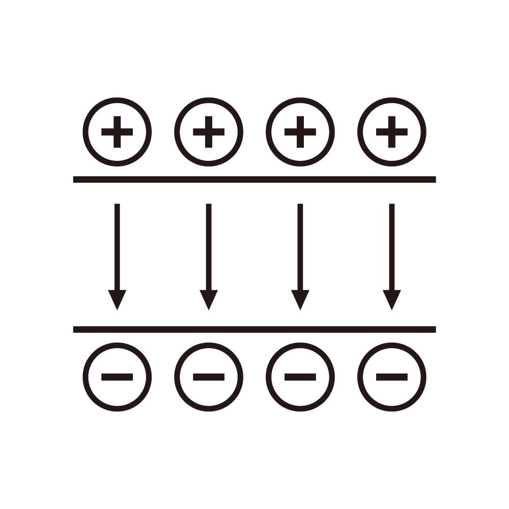
A supply that can reverse its polarity on command serves two different needs. In a laboratory doing electrostatic cycling experiments, the reversal is the experiment: the sample is charged positive, held, reversed, held, and the charge's decay is the measurement. On a production line running several electrostatic processes from one cabinet, the reversal is a way to reuse the hardware, with the polarity chosen by the recipe rather than by the experimenter.
The experimental case's requirement is precision in the reversal's timing and symmetry. The sample's charge decay depends on the field's duration and magnitude, and an asymmetry of a few percent between the positive and negative phases biases the decay curve. The bias is invisible unless the two phases are compared directly, and it is the reason a supply with a single setpoint for both polarities is unsuitable: the positive and negative rails have different load impedances and different leakage, so a single setpoint gives two different actual voltages.
The production case's requirement is speed of changeover and safety during the change. Changing polarity on a process line means the electrode's potential goes from positive to negative, and the electrodes are often exposed to operators during a changeover. The supply's reversal sequence must therefore include a verified discharge, a visible indication, and an interlock that prevents the operator from reaching the electrode until the discharge is confirmed. The confirmation should be a measurement at the electrode, not a timer.
Symmetry is achieved in two ways: a bipolar topology with a single transformer and two rectifier chains, or two independent supplies with a switching matrix. The first is compact and cheap but shares a common point, which means the leakage paths are shared and the symmetry depends on matched components. The second is larger and more expensive but each polarity has its own feedback, so symmetry is enforced by the control loop rather than by component matching. For experiments, the second is usually the right choice; for production, the first is often adequate if the recipe's tolerance is loose.
The changeover's transient is the part that damages samples and products. When the polarity reverses, the load's capacitance must be discharged and then charged in the opposite direction, and the discharge's current flows through whatever path is available. A supply with a controlled reversal ramps the voltage down to zero, holds at zero for a defined interval, then ramps up in the opposite direction; the ramp's rates are settable, and the hold interval is long enough that any stored charge in the load has decayed through the load's own resistance. A supply that switches abruptly produces a current spike that can damage thin films and can trip the supply's own protection.
In electrostatic cycling experiments, the hold interval matters because the sample's charge decay continues during it. A hold of a second is a measurable part of the experiment's time base, so the interval must be known accurately and logged with the data. A supply that does not report the interval's actual duration, as opposed to its setpoint, leaves an unknown in the analysis.
Multi-process lines add a complication: the same cabinet serves processes with different load capacitances, from a small electrode in a corona treater to a large roll in a web process. The reversal's ramp rate that is appropriate for the small load is too fast for the large one, and the current limit that protects the small load will slow the large load's reversal unacceptably. The practical solution is a recipe table that carries the ramp rate and the current limit for each process, selected automatically when the recipe is loaded. The table's entries should be validated at commissioning and re-validated whenever a load changes.
Leakage asymmetry is the most common field complaint. The positive rail and the negative rail have different insulation paths, and after a few months the paths' leakage differs because one side has seen more contamination. The symptom is that the positive voltage reads correctly while the negative reads high or low by a few percent, and the correction is usually to adjust the setpoint of the weaker rail. Adjusting the setpoint masks the leakage, and the mask fails when the contamination grows. Measuring the leakage on each rail at a maintenance interval, and cleaning when the two differ by more than a threshold, is the better practice.
Corona in the negative polarity is more energetic than in the positive, because negative corona produces more current for the same field. In a corona treater, this means the negative phase does more treatment work, and the experimenter who wants symmetric treatment must either shorten the negative phase or lower its voltage. The supply can support this with independent setpoints for each polarity, which is exactly the feature the single-setpoint design lacks. Independent setpoints are also useful for compensating the asymmetry caused by the load's geometry.
The electrode's geometry interacts with the polarity. A sharp edge that is stable in positive polarity may produce a strong corona in negative, and the resulting current can be several times larger. The supply's protection must therefore be set for the worst polarity, which means the positive phase runs with more margin than it needs. A supply with per-polarity limits avoids this compromise, and the cost is a slightly more complex control.
Ozone generation is a side effect worth mentioning for corona processes. Negative corona produces more ozone per unit of charge, and ozone attacks the insulation and the electrode. In a cabinet that serves both polarities, the insulation's ozone exposure is higher than a single-polarity design's, and the insulation's material must be chosen accordingly. Silicone rubber and certain fluoropolymers resist ozone; polyurethane does not.
Reversal frequency affects the supply's thermal design. At a high reversal rate, the supply's output stage dissipates more because each reversal involves charging and discharging the load's capacitance, and that energy is lost in the supply's own components unless it is recovered. A reversal rate of a few per second is unremarkable; a rate of tens per second makes the recovery circuit worthwhile. The recovery's efficiency, measured as the ratio of energy returned to the bus to energy removed from the load, is the parameter that determines whether the saving is real.
The measurement of the reversal's symmetry is best done with a differential probe across the load, with the supply's own readings logged alongside. The probe shows the actual waveform, including the hold interval and the ramps, and comparing the two polarities' waveforms reveals asymmetries that the supply's readings cannot. The probe's bandwidth must be adequate for the fastest ramp, which for a large load's reversal is a few hundred volts per millisecond.
For a laboratory, the experiment's repeatability is what sells the equipment. Two runs with the same settings should produce the same decay curve within the noise. If they do not, the usual cause is the hold interval's variability, which comes from the supply's control loop's settling time being different for the two polarities. Logging the actual interval, and correcting for it in the analysis, is a workaround; making the supply's settling symmetric is the fix.
The narrow conclusions: independent setpoints per polarity, a controlled reversal with a logged hold interval, per-recipe ramp and limit tables, and leakage measurement on each rail. Those four items cover the differences between a supply that supports the work and one that the work has to be designed around.
A practical note on the changeover procedure: the discharge should be verified at the electrode with a probe that has its own reference, not by reading the supply's voltmeter. The supply's voltmeter reads the output terminal, and the electrode's potential can lag if the cable's capacitance is large. A probe at the electrode is the only measurement that tells the operator it is safe to reach in, and the procedure should be written around that probe rather than around the supply's display.
Recipe tables age badly if they are not maintained. A new electrode's geometry, a different polymer, or a replaced cable all change the load, and a recipe that was validated for the old load will produce a reversal that is too fast or too slow. Marking each table entry with the load it was validated for, and refusing to load an entry whose validation tag does not match the installed hardware's tag, prevents the common failure of running a validated recipe against unvalidated hardware.
One more consideration for experiments: the reversal's symmetry should be verified at the start of each campaign, not only at commissioning. The verification is a run with a resistive load at both polarities, comparing the actual voltages with a calibrated meter. A few minutes of work at the start of a campaign establishes that the instrument's baseline has not moved, which is the assumption every later comparison depends on.
A final note on the two applications' economics: the laboratory values repeatability and will pay for independent rails, while the production line values changeover time and will pay for a shared transformer with a fast sequencer. Choosing between them is not a matter of quality but of which cost the customer is actually carrying, and a supplier that provides both architectures with the same control interface lets the customer decide per tool rather than per vendor.