











静电植绒高压电源在功能纺织与汽车面料中的参数优化
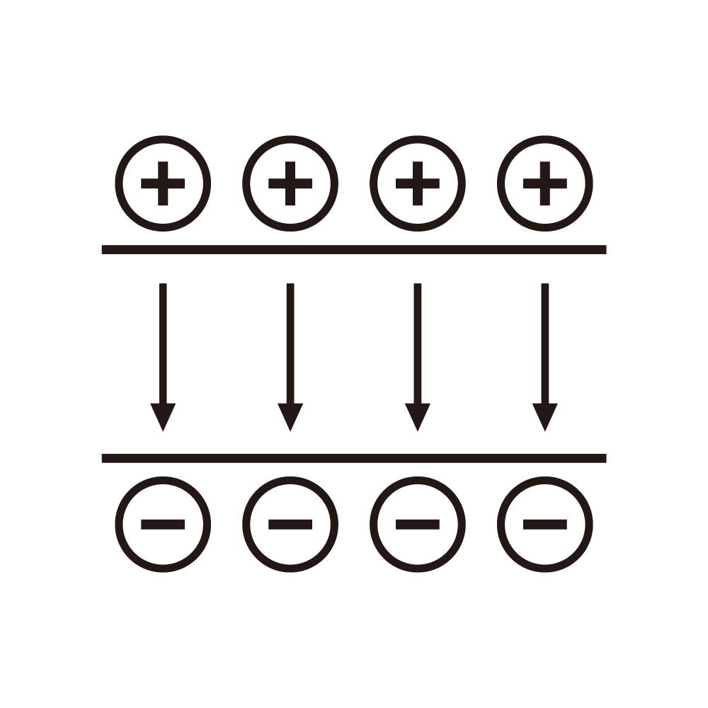
Electrostatic flocking builds a standing field between a grounded substrate and a charged hopper, and the fibres are launched along the field lines until they strike the adhesive layer at right angles. The angle matters because a fibre that lands at an inclination stands up less on cure and the pile loses body. The supply therefore controls not only the field strength but also the field geometry, and the geometry is set by the electrode arrangement far more than by the voltage number.
Three parameters dominate the practical work. The first is the field strength at the substrate, which must be high enough to accelerate the fibre to a velocity that overcomes the air drag in the gap but low enough that the fibre does not bend on impact. The second is the corona current at the hopper, which charges the fibres and also ionizes the air; too much current produces a space charge that distorts the field near the substrate and turns the impact angle into a scatter. The third is the field stability over a shift, because adhesive viscosity and humidity both change and the field must be trimmed to follow them.
A typical functional textile line runs at a substrate speed of twenty to forty metres per minute, and the field must be continuous across the full width within a tolerance of a few percent. The supply usually drives a segmented electrode through a resistive ladder, and the tolerance is limited by the ladder trim rather than by the regulator. Trimming the ladder against a reference at assembly and checking the trim with a field probe every quarter keeps the tolerance within reach, and the probe check also catches a segment that has lost contact.
Automotive fabric is a harder case. The adhesive is often a two-component system with a short pot life, and the field must be raised at the moment the adhesive enters the gap and lowered as it cures, because a strong field on a cured layer attracts dust rather than fibre. A programmed profile with an initial boost of a few seconds, a plateau for the flocking window and a ramp down at the end of each panel meets the requirement, and the profile can be triggered from the panel sensor rather than from a timer, which removes the drift between mechanical and electrical timing.
Corona current control is usually a separate loop from the field loop, because the two interact. Raising the corona current raises the space charge, which reduces the effective field at the substrate at constant electrode voltage, so a field loop alone would compensate by raising the electrode voltage and the current would climb again. A cascade structure, with a slow field loop outside a fast current loop, converges without that interaction, and the time constants should differ by a factor of at least ten for the cascade to stay stable.
Humidity changes the corona onset and the fibre conductivity, and both change the charge-to-mass ratio. A line that runs well in the morning can produce a matted pile in the afternoon when the relative humidity rises twenty points. The practical response is a humidity sensor at the enclosure and a compensation table that trims the corona current and the field together, so the charge-to-mass ratio stays inside the window where the fibres stand up. The table is built once from trials and then verified seasonally.
Safety and cleanliness shape the hardware. The hopper carries a high voltage in an area where operators load fibre by hand, so the interlock must remove the field before the access door is more than a hand width open. The corona discharge also produces ozone, and the enclosure needs extraction sized for the current; a low current keeps the ozone below the working limit, which is one more reason to control the current rather than to run the supply at its maximum.
Dust and fibre accumulation on insulators is the most common cause of a sudden field collapse. The path along a fouled insulator carries a leakage current that the supply reads as load, and the field sags before any alarm appears. A leakage current monitor that watches the trend rather than the absolute value catches the problem two shifts before the collapse, which is enough time to schedule a cleaning without stopping the line.
The control cabinet should record the field, the corona current, the humidity and the leakage trend for each panel. That record turns a pile complaint into a comparison between panels, and the comparison usually shows which parameter moved first. Without the record the same complaint is argued from memory, and memory is a poor instrument.
Parameter optimisation in this application is therefore a matter of matching three loops to one another and to the material, and of keeping a record that shows when the match has slipped. The supply is the actuator, not the answer, and a line that treats the supply as the answer spends its time re-tuning instead of producing.
Field uniformity across the working width is the next practical problem. A ladder of resistors feeding segmented electrodes distributes the voltage, but the segments at the ends of the ladder see a longer path through the bus bar and the field droops at the selvage. The droop shows up as a thinner pile along the edges, and the customer rejects the roll for it. Correcting the droop by tapering the ladder resistances costs nothing extra at assembly and removes the defect permanently, whereas correcting it by raising the overall voltage merely moves the droop inward and wastes field in the centre.
Grounding deserves equal care. The substrate drum is the ground reference for the fibre trajectory, and any impedance between the drum and the supply return tilts the field. A drum bearing that has dried out can present several ohms at the flocking frequency, and the tilt moves the pile out of perpendicular by a few degrees across the width. Measuring the drum-to-return impedance at each service and specifying a limit of half an ohm catches the drift before the reject rate climbs.
Adhesive thickness interacts with field strength in a way that is easy to miss. A thin adhesive layer means the fibre tip meets the substrate sooner, so the field accelerates the fibre for a shorter distance and the impact velocity falls; the fibre lands soft and the pile lacks the crisp stand that the specification asks for. Raising the field to compensate works until the thin coated areas begin to show corona marks, and the marks are a permanent defect. A thickness sensor coupled to the field setpoint gives a small correction that follows the coating profile, and it is far cheaper than the scrap it prevents.
Temperature is the slow variable in the process. The adhesive cures exothermically and the platen warms through a shift, and a warm platen lowers the adhesive viscosity, which changes the penetration depth of the fibre tip. A field trim of a few percent per ten degrees keeps the penetration constant, and a platen temperature probe near the entry of the flocking zone is enough to drive the trim.
Cleaning the electrodes is part of the parameter set, not a separate maintenance topic. Loose fibre collects on the electrode edges, and the collected fibre sharpens the local field, which raises the corona current and distorts the space charge. A scheduled clean at the start of each shift, with a field probe check afterwards, keeps the current where the table expects it. Skipping the clean shows up as a current that creeps upward through the shift and a pile that gradually loses stand.
For automotive panels the tolerance on field stability is tighter than for apparel because the panels are inspected under raking light, where a small variation in stand height reads as a streak. Two measures bring the variation within tolerance. The first is a reference electrode inside the enclosure that measures the field directly, so the loop closes on the actual field rather than on the supply output. The second is a panel-edge detector that gates the profile so the boost and the ramp occur at the same physical position on every panel, independent of conveyor speed. The pair removes the streak that otherwise appears when conveyor speed changes between batches.
Commissioning should record a field map across the width and along the run for the first ten panels. The map is the baseline for every later comparison, and it converts a subjective judgement about pile quality into a number that can be trended. Trending is what keeps a line productive over years, because the failure modes of a flocking line are slow and the operator notices only after the reject rate has already risen.
A shift that ends with the pile still standing is a shift that matched the loops to the material all the way through, and the record is what proves it.
Standing pile is the only evidence the customer accepts, and the field record is the only evidence the engineer can use.