Improvement of Voltage-Frequency Synchronous Regulation Algorithm for Variable Frequency, Variable Voltage, and Regulated Power Supplies
Introduction
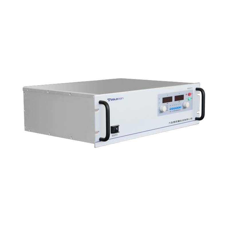
Variable frequency, variable voltage, and regulated power supplies (VFVV regulated power supplies) are essential equipment in fields such as motor drive, marine electrical systems, and power grid simulation. In these applications, the voltage and frequency of the power supply need to be adjusted synchronously. For example, in the variable-speed motor drive, the motor voltage must be proportional to the frequency (V/f ratio control) to ensure constant magnetic flux; in the power grid simulation, it is necessary to simulate the voltage and frequency fluctuations of the power grid (e.g., voltage sag with frequency drop) synchronously. However, traditional voltage-frequency synchronous regulation algorithms have problems such as strong coupling between voltage and frequency adjustment, slow synchronous response, and poor stability under load disturbances, which affect the performance of the power supply.
Core Technical Challenges
The main challenges of voltage-frequency synchronous regulation include three aspects. First, the coupling between voltage and frequency adjustment. In the traditional algorithm, the voltage and frequency are adjusted by the same control loop, and a change in one parameter will affect the other. For example, when adjusting the frequency to increase the motor speed, the voltage may overshoot due to the coupling, leading to motor overheating. Second, the slow synchronous response. The traditional PI control loop has a narrow bandwidth, and when the set voltage or frequency changes suddenly, the loop takes a long time to reach the steady state, resulting in asynchronous adjustment of voltage and frequency. Third, the poor anti-disturbance ability. Load changes (e.g., motor load torque increase) will cause both voltage and frequency to deviate from the set values, and the traditional algorithm cannot adjust the two parameters synchronously and quickly to suppress the disturbance.
Improved Synchronous Regulation Algorithm
Decoupled Control Based on dq Transformation
To solve the coupling problem between voltage and frequency, a decoupled control strategy based on dq transformation is proposed. The three-phase AC output voltage and current of the VFVV regulated power supply are transformed into two DC components (d-axis and q-axis) in the rotating coordinate system through Park transformation. In the dq coordinate system, the voltage and frequency can be adjusted independently, realizing decoupling.
The d-axis is used for voltage control. The d-axis voltage component (V_d) is proportional to the output voltage amplitude, and the control system adjusts V_d through a PI controller to make the output voltage amplitude track the set value. The q-axis is used for frequency control. The q-axis voltage component (V_q) is related to the output frequency, and the frequency is adjusted by changing the angular velocity (ω) of the rotating coordinate system. The angular velocity is calculated by integrating the frequency set value (f_set), and the q-axis controller adjusts V_q to ensure that the actual angular velocity tracks the calculated value.
In addition, a cross-coupling compensation term is added to the dq decoupled control. The cross-coupling between the d-axis and q-axis is modeled, and the compensation voltage (V_dc and V_qc) is calculated according to the actual current components (I_d and I_q). The compensation voltage is added to the output of the d-axis and q-axis PI controllers to further eliminate the residual coupling, ensuring that the voltage and frequency adjustment are completely independent.
Model Predictive Control for Fast Synchronous Response
To improve the synchronous response speed, a model predictive control (MPC) algorithm is integrated into the decoupled control system. The MPC algorithm predicts the future states of the power supply (output voltage, frequency, and current) based on the mathematical model of the VFVV regulated power supply and the current system state, and optimizes the control signal to minimize the tracking error of voltage and frequency.
First, the discrete-time state space model of the power supply is established, including the inverter, output filter, and load. The state variables are the output voltage (V_o), output frequency (f_o), and output current (I_o). The input variable is the PWM control signal of the inverter. Then, the MPC algorithm defines a cost function that includes the voltage tracking error (ΔV = V_set - V_o), frequency tracking error (Δf = f_set - f_o), and control signal change rate (to avoid excessive switching of power devices). The cost function is expressed as:
J = λ_V × ΔV² + λ_f × Δf² + λ_u × Δu²
where λ_V, λ_f, and λ_u are the weight coefficients (calibrated through experiments to balance the importance of voltage, frequency, and control stability).
The MPC algorithm solves the optimization problem of minimizing J over a finite prediction horizon (e.g., 5 steps) and applies the first step of the optimized control signal to the inverter. This predictive control method can adjust the voltage and frequency in advance according to the set value change, significantly improving the synchronous response speed.
Disturbance Observer for Anti-Disturbance Stability
To enhance the anti-disturbance ability of the synchronous regulation system, a disturbance observer (DOB) is designed. The DOB estimates the external disturbances (such as load torque changes and power grid voltage fluctuations) based on the input and output signals of the power supply, and generates a compensation signal to offset the impact of the disturbances.
The DOB uses the transfer function of the power supply (G(s)) and a low-pass filter (F(s)) to estimate the disturbance (d). The estimation formula is:
d̂(s) = (1 - G(s) × F(s)) / G(s) × u(s) + F(s) × y(s)
where u(s) is the control input, y(s) is the system output (voltage or frequency), and d̂(s) is the estimated disturbance.
The estimated disturbance is converted into a compensation voltage and a compensation frequency, which are added to the set voltage and set frequency of the control system, respectively. For example, when the motor load torque increases (disturbance), the output voltage drops and the frequency decreases. The DOB estimates this disturbance and increases the set voltage and set frequency slightly, so that the control system adjusts the output voltage and frequency synchronously to suppress the disturbance.
Application Verification
A VFVV regulated power supply (output voltage 0-400V, frequency 0.1Hz-1kHz) is used to test the improved synchronous regulation algorithm. The test includes three scenarios: step change of set voltage/frequency, load disturbance, and V/f ratio control.
In the step change test, the set voltage is changed from 220V to 380V, and the set frequency is changed from 50Hz to 60Hz synchronously. The test results show that the improved algorithm reaches the steady state within 50ms, and the voltage and frequency overshoot are less than 2% (the traditional algorithm takes 200ms to reach steady state, with overshoot of 8%-10%).
In the load disturbance test, the motor load torque is increased from 50% to 100% of the rated value suddenly. The improved algorithm suppresses the voltage drop (from 220V to 218V) and frequency drop (from 50Hz to 49.8Hz) within 30ms, and the voltage and frequency return to the set values within 50ms (the traditional algorithm has a voltage drop of 10V and a frequency drop of 0.5Hz, and takes 150ms to recover).
In the V/f ratio control test (used for motor drive), the V/f ratio is set to 4.4V/Hz (220V/50Hz). When the frequency is adjusted from 10Hz to 50Hz, the voltage is adjusted synchronously from 44V to 220V. The test shows that the V/f ratio error of the improved algorithm is less than 0.5% (the traditional algorithm is 2%-3%), ensuring that the motor magnetic flux remains constant and the motor runs smoothly.
Conclusion
The improved voltage-frequency synchronous regulation algorithm based on dq decoupled control, MPC, and DOB effectively solves the problems of coupling, slow response, and poor anti-disturbance ability in traditional algorithms. It realizes fast and accurate synchronous regulation of voltage and frequency, and provides a high-performance control solution for VFVV regulated power supplies in motor drive, marine, and power grid simulation applications.


