Pulse Pileup Correction Algorithm and Image Quality of High Voltage Power Supply for Photon Counting CT
Photon counting computed tomography represents a transformative advance in X-ray imaging technology, offering potential improvements in spatial resolution, contrast resolution, and material differentiation compared to conventional energy integrating detectors. These systems detect individual X-ray photons and measure their energy, enabling spectral imaging and elimination of electronic noise. The high voltage power supply that powers the X-ray tube determines the X-ray spectrum and flux, with pulse characteristics affecting the photon counting performance. At high photon fluxes, pulse pileup occurs when multiple photons arrive within the detector response time, causing counting losses and energy measurement errors. Correction algorithms for pulse pileup are essential for maintaining image quality at clinically relevant flux levels.
Photon counting detectors convert individual X-ray photons into electrical pulses with amplitudes proportional to the photon energy. Pulse processing electronics measure the pulse amplitude and increment counters in energy bins corresponding to different energy ranges. The count rates in each energy bin provide the spectral information that enables material decomposition and enhanced contrast. The ideal detector would count every photon and accurately measure every energy, but practical limitations cause deviations from this ideal.
Pulse pileup occurs when a second photon arrives before the processing of a previous photon is complete. The detector and electronics have a finite response time determined by the charge collection time, the pulse shaping time, and the digitization time. During this response time, the system is processing the first photon and cannot properly process additional photons. Depending on the arrival time separation, the second photon may be completely missed, may be counted with incorrect energy, or may merge with the first photon to produce a single pulse with combined energy.
The pileup effects depend on the photon arrival rate and the detector response time. At low rates, the probability of pileup is small and the counting is nearly ideal. As the rate increases, pileup becomes more frequent, causing counting losses and spectral distortion. The counting losses reduce the detected counts relative to the incident photons, affecting the quantitative accuracy of the measurement. The spectral distortion shifts counts between energy bins, affecting the material decomposition accuracy.
Paralyzable and non paralyzable detector models describe different pileup behaviors. In a paralyzable detector, a photon arriving during the processing of a previous photon extends the dead time, potentially causing extended periods of insensitivity at high rates. In a non paralyzable detector, photons arriving during dead time are simply lost without extending the dead period. Real detectors may exhibit behavior between these idealized models depending on the specific pulse processing architecture.
Pulse pileup correction algorithms estimate the incident photon rate and spectrum from the measured counts, compensating for the pileup losses. Model based corrections use the known detector response characteristics to predict the pileup effects and invert the relationship between incident and measured counts. The correction requires knowledge of the detector dead time and the pileup model appropriate for the specific detector. Statistical approaches use the measured count distribution to estimate the incident rate without detailed detector modeling.
The accuracy of pileup correction affects the image quality in photon counting CT. Incomplete correction leaves residual counting losses that appear as artifacts in the reconstructed images. The artifacts may include cupping in uniform regions, streaks from high attenuation objects, and errors in material decomposition images. Overcorrection can produce opposite artifacts. The correction accuracy requirements depend on the clinical application and the acceptable level of artifacts.
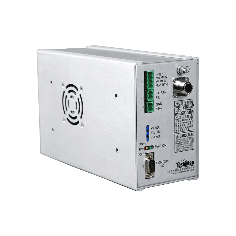
The high voltage power supply affects the pileup through the X-ray flux and spectrum. Higher tube voltages produce X-rays with higher energy and different spectral shape. Higher tube currents produce higher photon flux, increasing the pileup rate. The power supply must provide stable voltage and current to maintain consistent X-ray output, enabling consistent pileup correction. Variations in output cause variations in pileup that may not be correctly compensated by corrections based on nominal operating parameters.
Pulse shaping in the detector electronics affects the pileup characteristics. Longer pulse shaping times improve the energy resolution by reducing noise but increase the dead time and pileup. Shorter shaping times reduce pileup but degrade energy resolution. The optimal shaping time balances the energy resolution and count rate capability for the specific application. Adaptive pulse shaping that adjusts based on the count rate can optimize performance across varying conditions.
Multi threshold photon counting uses multiple energy thresholds to sort photons into energy bins. Pileup can cause photons to be counted in incorrect bins when the pulse amplitude is distorted by pileup. The correction algorithm must account for the spectral distortion as well as the counting losses. The correction becomes more complex with more energy bins, as the counts can shift between multiple bins in various ways depending on the pileup scenario.
Real time implementation of pileup correction requires sufficient computational speed to process the count data at the acquisition rate. The correction calculations may involve iterative algorithms or lookup tables derived from the pileup model. The implementation must fit within the data processing pipeline of the CT system, potentially in the detector electronics, the data acquisition system, or the reconstruction computer. The computational requirements increase with the number of energy bins and the complexity of the correction model.
Validation of pileup correction requires measurements under controlled conditions with known incident flux. Phantoms with known composition and geometry provide test objects where the expected measurements can be calculated from the known properties. Comparison of corrected measurements with expected values reveals any residual errors in the correction. Measurements across a range of flux levels test the correction under varying pileup conditions. Clinical images with independent validation provide the ultimate test of the correction effectiveness for diagnostic applications.